2.
Check the core switch blade status by entering the
slotShow
and
haShow
commands.
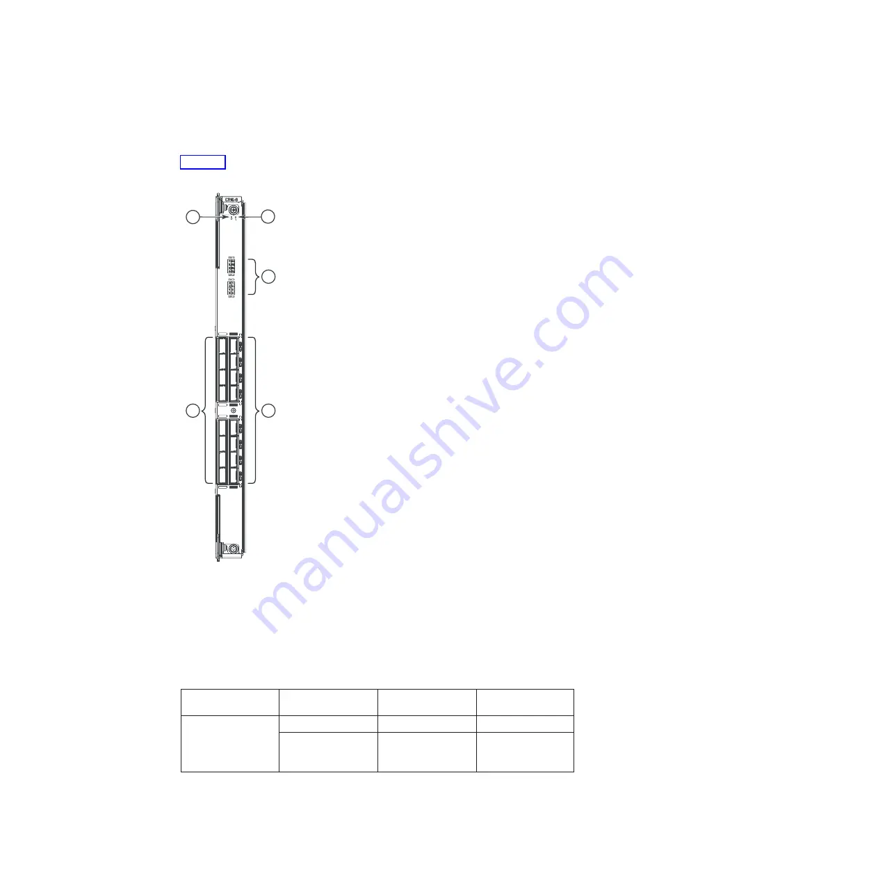
Figure 25 identifies the core switch blade and its components
1
Power LED
4
QSFP connectors
2
Status LED
5
QSFP connector status LEDs
3
QSFP port map and trunking
diagram
Table 9. CR16-8 blade LED descriptions
LED purpose
Color
Status
Recommended
Action
Power
Steady green
CR16-8 blade is on
No action required.
No light (LED is off)
CR16-8 blade is not
on
Ensure that the blade
is firmly seated and
has power.
2
1
4
3
5
B768ig066
Figure 25. Core switch blade (CR16-8), LEDs and QSFP connectors
Chapter 4. Monitoring system components
73
Содержание SAN768B-2
Страница 2: ......
Страница 8: ...vi SAN768B 2 Installation Service and User Guide...
Страница 10: ...viii SAN768B 2 Installation Service and User Guide...
Страница 14: ...xii SAN768B 2 Installation Service and User Guide...
Страница 28: ...xxvi SAN768B 2 Installation Service and User Guide...
Страница 40: ...12 SAN768B 2 Installation Service and User Guide...
Страница 108: ...80 SAN768B 2 Installation Service and User Guide...
Страница 182: ...154 SAN768B 2 Installation Service and User Guide...
Страница 186: ...158 SAN768B 2 Installation Service and User Guide...
Страница 196: ...168 SAN768B 2 Installation Service and User Guide...
Страница 202: ...174 SAN768B 2 Installation Service and User Guide...
Страница 220: ...192 SAN768B 2 Installation Service and User Guide...
Страница 226: ...198 SAN768B 2 Installation Service and User Guide...
Страница 227: ......
Страница 228: ...Part Number 00MA746 Printed in USA GA32 0893 06 1P P N 00MA746...


