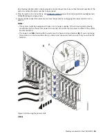
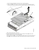


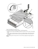
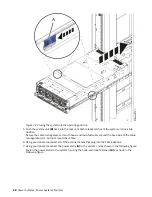
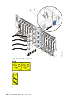

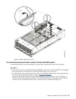
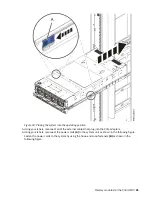

Figure 21. Placing the system into the operating position
5. Push the system unit (B) back into the rack until both release latches of the system unit lock into
position.
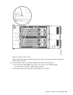
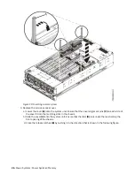
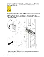
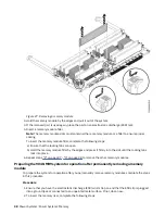
Secure the cable management arm with hook-and-loop fasteners around the back side of the cable
management arm, but not around the cables.
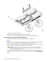
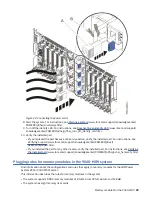
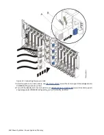
6. Using your labels, reconnect all of the external cables that plug into the PCIe adapters.
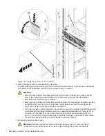
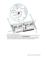
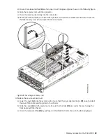
7. Using your labels, reconnect the power cords (A) to the system unit as shown in the following figure.
Fasten the power cords to the system by using the hook-and-loop fasteners (B) as shown in the
following figure.
28 Power Systems: Power Systems: Memory
Содержание Power System System E950
Страница 1: ...Power Systems Memory modules for the 9040 MR9 IBM...
Страница 4: ...iv...
Страница 14: ...xiv Power Systems Power Systems Memory...
Страница 17: ...Figure 1 Removing the power cords L003 or or Memory modules for the 9040 MR9 3...
Страница 30: ...or or or or 16 Power Systems Power Systems Memory...
Страница 46: ...Figure 23 Removing the power cords L003 or or 32 Power Systems Power Systems Memory...
Страница 59: ...Figure 32 Removing the power cords L003 or or Memory riser for the 9040 MR9 45...
Страница 70: ...Figure 40 Removing the power cords L003 or or 56 Power Systems Power Systems Memory...
Страница 86: ...or or or or 72 Power Systems Power Systems Memory...
Страница 105: ......
Страница 106: ...IBM...


