6.
If you are removing more than one drive, repeat the steps in this procedure until all drives are
removed.
7.
If you are not installing a replacement drive, install a filler in the empty slot to ensure proper air
flow for cooling. For instructions, see“Installing a disk drive filler in the 5148-21L, 5148-22L,
8247-21L, 8247-22L, 8284-21A, or 8284-22A” on page 99.
8.
If you are installing a replacement drive as a replacement for the failed disk drive or solid-state
drive, go to “Replacing a disk drive or solid-state drive in the 8284-21A or 8284-22A system with the
power turned on in AIX” on page 54.
9.
If you are removing an SSD in an expanded function system, continue with the next step.
10.
Remove the front cover to access the SSD. For instructions to remove the front cover from an
expanded function system, see “Removing the front cover from a rack-mounted 5148-21L, 5148-22L,
8247-21L, 8247-22L, 8284-21A, or 8284-22A system” on page 148.
11.
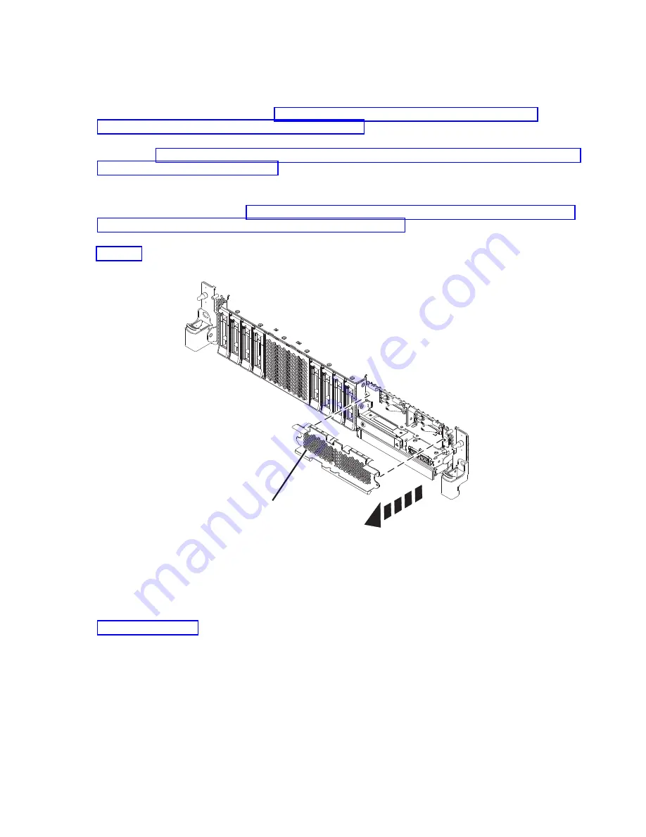
To access the SSD slots, remove the perforated plate (B) covering the SSD cage as shown in
Figure 52.
12.
When the identify LED turns on solid, unlock the drive bay handle (B) by pushing the handle latch
(A)
in the direction that is shown and pulling the drive bay handle (B) out toward you, as shown in
Figure 53 on page 54. If the handle is not all the way out, the solid-state drive cannot slide out of the
system.
P8HAL516-2
B
Figure 52. Removing the SSD cage cover to access the SSD slots in an expanded function system
Disk drives or solid-state drives
53
Содержание Power System 5148-21L
Страница 2: ......
Страница 18: ...xvi Disk drives or solid state drives ...
Страница 202: ...184 Disk drives or solid state drives ...
Страница 203: ......
Страница 204: ...IBM ...


