4.
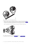
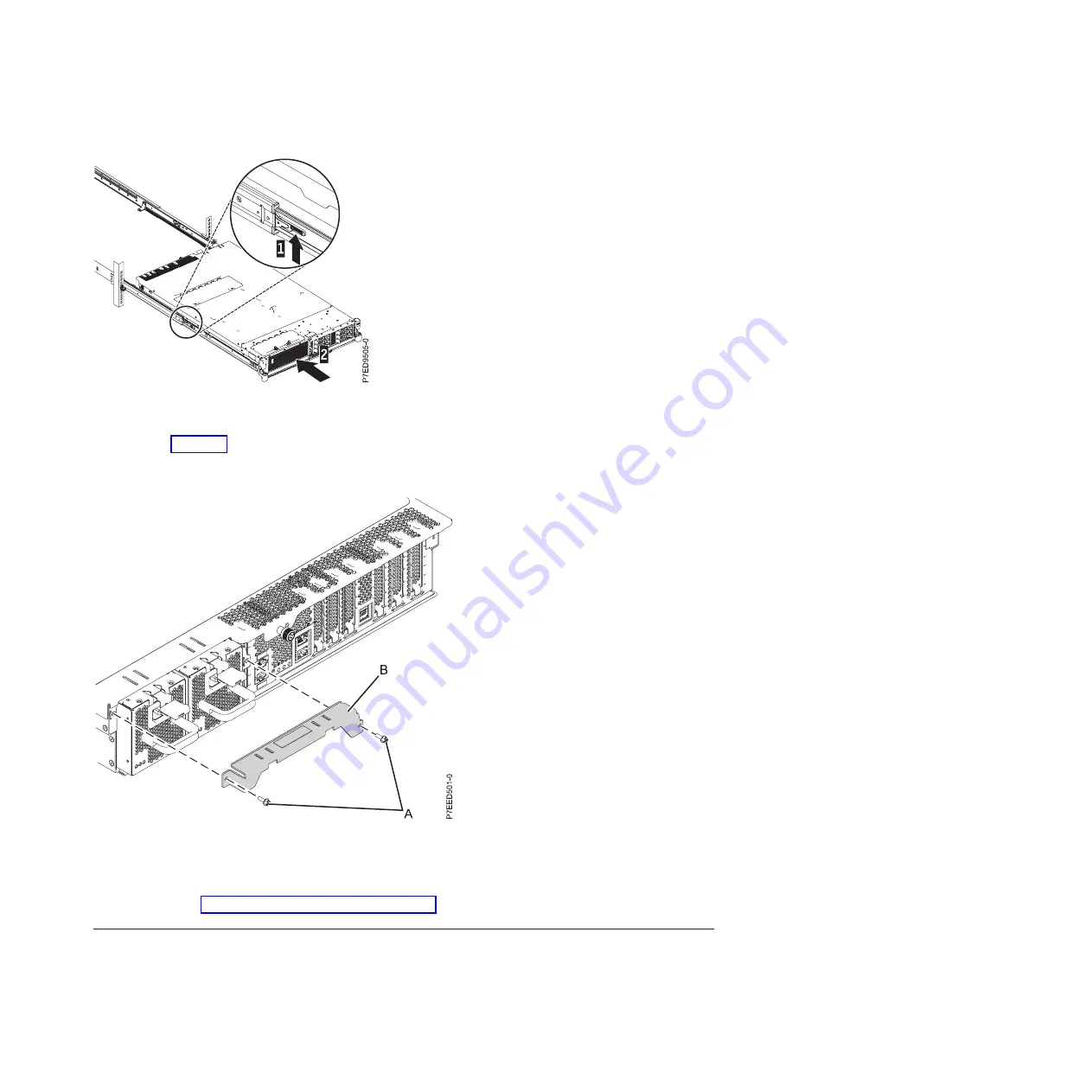
Remove the shipping bracket that is on the left side of the rear of the system before you cable it, as
shown in Figure 10. To remove the shipping bracket, complete the following steps:
a.
Remove the two screws (
A
).
b.
Pull the bracket off of the system (
B
) and discard.
c.
Push the power supplies back into the system, ensuring that they are fully seated and latched.
5.
Continue with “Installing the cable-management arm.”
Installing the cable-management arm
You might need to install the cable-management arm. Use this procedure to perform this task.
To install the cable-management arm, complete the following steps:
Figure 9. Release latches and server
Figure 10. Shipping bracket removal
Installing the server into a rack
9
Содержание POWER 730
Страница 2: ......
Страница 6: ...iv Power Systems Installing the IBM Power 710 Express 8231 E1C or IBM Power 730 Express 8231 E2C...
Страница 36: ...24 Power Systems Installing the IBM Power 710 Express 8231 E1C or IBM Power 730 Express 8231 E2C...
Страница 57: ......
Страница 58: ...Part Number 00L5066 Printed in USA GI11 9861 03 1P P N 00L5066...


