v
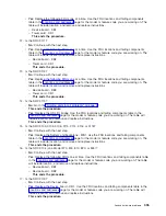
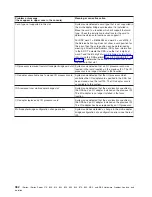
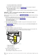
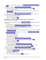
The
cable
from
the
UEPO
to
the
BPC
on
the
side
referenced
by
the
error
code
that
sent
you
to
this
procedure.
See
symbolic
FRU
v
BPCPWR
on
the
side
referenced
by
the
error
code
that
sent
you
to
this
procedure.
See
symbolic
FRU
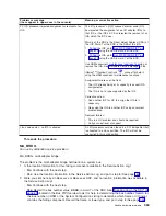
After
each
FRU
is
exchanged,
is
the
error
code
that
sent
you
here
still
reported?
v
No:
The
problem
has
been
corrected.
See
This
ends
the
procedure.
v
Yes:
Exchange
the
next
FRU
in
the
list.
If
all
of
the
FRUs
have
been
exchanged,
then
call
your
next
level
of
support.
This
ends
the
procedure.
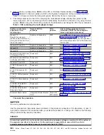
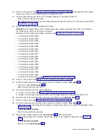
5.
Perform
the
following
actions
one
at
a
time:
a.
Replace
the
UEPO
card
assembly.
See
for
the
part
number
and
a
link
to
the
remove
and
replace
procedure.
Then,
continue
with
step
6
(See
page
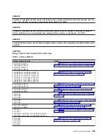
b.
Check
with
the
customer’s
site
services
to
test
the
room
EPO
for
correct
operation.
When
the
room
EPO
is
working
correctly,
reconnect
the
cable
by
performing
the
following
steps:
1)
Set
the
UEPO
switch
on
both
bulk
power
controllers
(BPCs)
to
the
BYPASS
position.
2)
Reconnect
the
customer’s
room
EPO
cable.
3)
Set
the
UEPO
switch
on
both
BPCs
back
to
the
NORMAL
position.
4)
Press
the
(white)
Service
complete
button.
5)
Continue
with
step
6
(See
page
6.
After
each
action
is
performed
in
step
4,
is
the
error
code
that
brought
you
here
reported?
v
No:
The
problem
has
been
corrected.
See
This
ends
the
procedure.
v
Yes:
Perform
the
next
action
on
the
list.
If
all
actions
have
been
performed,
then
call
your
next
level
of
support
for
assistance.
This
ends
the
procedure.
MAPPWR-4:
There
is
a
350
V
bulk
failure
For
use
by
authorized
service
providers.
Note:
Read
the
Danger
and
caution
notices
in
the
introduction
before
performing
this
procedure.
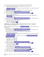
1.
This
problem
can
be
caused
by
the
bulk
power
distribution
(BPD)
plugged
into
the
failing
bulk
power
assembly
(BPA).
Check
all
the
BPDs
on
the
side
of
the
BPA
(A
or
B)
referenced
by
the
error
code
that
sent
you
to
this
procedure.
FRUs
on
the
operating
side
of
the
BPA
(with
BPC
GOOD
LED
on)
must
not
be
disturbed
during
this
procedure.
Perform
the
following:
a.
Turn
all
the
BPR
on/off
switches
on
this
BPA
to
the
off
position
(to
the
right).
b.
If
there
is
more
than
one
BPD
left
to
be
checked,
start
with
the
uppermost
BPD.
Unplug
and
make
a
note
of
the
BPD
to
be
checked
and
carefully
pull
it
approximately
25
mm
(1
inch)
away
from
the
backplane
without
unplugging
any
cables.
See
the
symbolic
FRU
c.
Set
all
the
BPR
on/off
switches
on
this
BPA
to
the
on
position
(to
the
left).
Does
the
BPC
GOOD
LED
on
the
BPC
come
on
and
stay
on?
v
Yes:
Replace
the
BPD
that
is
currently
unplugged.
See
the
symbolic
FRU
Then,
see
This
ends
the
procedure.
v
No:
Perform
the
following:
a.
Turn
all
of
the
BPR
on/off
switches
on
this
BPA
to
the
off
position
(to
the
right).
b.
Replug
the
BPD.
Analyze
hardware
problems
369
Содержание iSeries Series
Страница 2: ......
Страница 504: ...492 iSeries iSeries Server 270 800 810 820 825 830 840 870 890 SB2 and SB3 Hardware Problem Analysis and Isolation...
Страница 508: ...496 iSeries iSeries Server 270 800 810 820 825 830 840 870 890 SB2 and SB3 Hardware Problem Analysis and Isolation...
Страница 511: ......
Страница 512: ...Printed in USA SY44 5914 01...

