N
ote:
Make
sure
that
you
review
and
understand
the
design
of
the
BladeCenter
unit.
Refer
to
the
following
documents
if
you
need
help
to
determine
your
system
configuration
re
q
uirements
and
the
bays
and
connectors
where
you
install
or
remove
components:
v
The
IBM
Eserver
BladeCenter
(Type
8677)
Planning
and
Installation
Guide
on
the
IBM
BladeCenter
Documentation
CD.
v
http://www.ibm.com/pc/support/
on
the
World
Wide
Web.
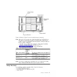
Table
1.
Power
module
and
power
module
bay
allocation
B
lade
server
installed
in:
M
inimum
number
o
f
power
modules
re
q
uired
Install
power
module
in
the
f
ollowin
g
power
module
bays:
Blade
bays
1
-6
O
ne
1
(
for
redundancy
you
can
install
a
second
power
module
in
power
module
bay
2
)
Blade
bays
7-
1
4
O
ne
3
(
for
redundancy
you
can
install
a
second
power
module
in
power
module
bay
4
)
N
ote:
Do
not
insert
a
blade
server
in
blade
bays
6/7.
This
is
because
the
blade
server
would
be
split
between
the
two
sets
of
power
modules.
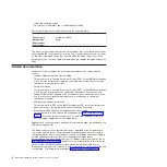
Usin
g
this
boo
k
This
Installation
and
User’s
Guide
provides
information
to
help
you:
v
Set
up
the
BladeCenter
QS20
v
Start
and
configure
the
BladeCenter
QS20
v
Install
options
Figure
2.
BladeCenter
Type
8677
rear
view
showing
the
power
module
bays
Chapter
1
.
Introduction
3
Содержание BladeCenter QS20
Страница 3: ...BladeCenter QS20 Type 0200 Installation and User s Guide SC33 8284 02...
Страница 28: ...14 BladeCenter QS20 Type 0200 Installation and User s Guide...
Страница 34: ...20 BladeCenter QS20 Type 0200 Installation and User s Guide...
Страница 58: ...44 BladeCenter QS20 Type 0200 Installation and User s Guide...
Страница 66: ...52 BladeCenter QS20 Type 0200 Installation and User s Guide...
Страница 86: ...72 BladeCenter QS20 Type 0200 Installation and User s Guide...
Страница 90: ...76 BladeCenter QS20 Type 0200 Installation and User s Guide...
Страница 91: ......
Страница 92: ...Part Number 43W7874 Printed in USA SC33 8284 02 1P P N 43W7874...


