The management module can display the most recent 32 SRCs and time stamps.
Manually refresh the list to update it.
Select
Blade Service Data
→
blade_name
in the management module to see a list of
the 32 most recent SRCs.
Table 15. Management module reference code listing
Unique ID
System Reference Code
Timestamp
00040001
D1513901
2005-11-13 19:30:20
00000016
D1513801
2005-11-13 19:30:16
Any message with more detail is highlighted as a link in the System Reference
Code column. Click the message to cause the management module to present the
additional message detail:
D1513901
Created at: 2007-11-13
19:30:20
SRC Version: 0x02
Hex Words 2-5: 020110F0 52298910 C1472000 200000FF
C1001F00 to C1645300 Service processor checkpoints
The C1xx progress codes, or checkpoints, offer information about the initialization
of both the service processor and the server. Service processor checkpoints are
typical reference codes that occur during the initial program load (IPL) of the
server.
Table 16 lists the progress codes that might be displayed during the power-on
self-test (POST), along with suggested actions to take if the system hangs on the
progress code. Only when you experience a hang condition should you take any of
the actions described for a progress code.
In the following progress codes,
x
can be any number or letter.
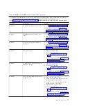
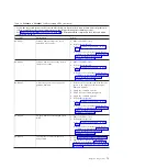
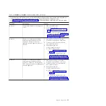
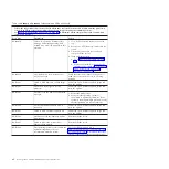
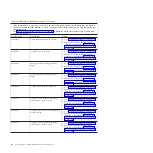
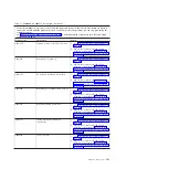
Table 16. C1001F00 to C1645300 checkpoints
v
If the system hangs on a progress code, follow the suggested actions in the order in which they are listed in
the Action column until the problem is solved. If an action solves the problem, you can stop performing the
remaining actions.
v
See Chapter 3, “Parts listing, Type 7998,” on page 235 to determine which components are CRUs and which
components are FRUs.
Progress code
Description
Action
C10010xx
Pre-standby
1.
Go to “Checkout procedure” on page 186.
2.
Replace the system-board and chassis
assembly, as described in “Replacing the
Tier 2 system-board and chassis assembly”
on page 274.
C1001F00
Pre-standby: starting initial transition
file
1.
Go to “Checkout procedure” on page 186.
2.
Replace the system-board and chassis
assembly, as described in “Replacing the
Tier 2 system-board and chassis assembly”
on page 274.
Chapter 2. Diagnostics
89
Содержание BladeCenter JS12
Страница 1: ...BladeCenter JS12 Type 7998 Problem Determination and Service Guide...
Страница 2: ......
Страница 3: ...BladeCenter JS12 Type 7998 Problem Determination and Service Guide...
Страница 14: ...xii JS12 Type 7998 Problem Determination and Service Guide...
Страница 248: ...234 JS12 Type 7998 Problem Determination and Service Guide...
Страница 252: ...238 JS12 Type 7998 Problem Determination and Service Guide...
Страница 290: ...276 JS12 Type 7998 Problem Determination and Service Guide...
Страница 298: ...284 JS12 Type 7998 Problem Determination and Service Guide...
Страница 302: ...288 JS12 Type 7998 Problem Determination and Service Guide...
Страница 312: ...298 JS12 Type 7998 Problem Determination and Service Guide...
Страница 317: ......
Страница 318: ...Part Number 60Y1568 Printed in USA 1P P N 60Y1568...


