background image

Chapter


2.


Installing


options


Important:


Before


you


install


optional


hardware,


make


sure


that


the


server


is


working


correctly.


Start


the


server,


and


make


sure


that


the


operating


system


starts,


if


an


operating


system


is


installed,


or


that


a


19990305


error


code


is


displayed,


indicating


that


an


operating


system


was


not


found


but


the


server


is


otherwise


working


correctly.


If


the


server


is


not


working


correctly,


see


the


Problem


Determination


and


Service


Guide


for


diagnostic


information.


This


chapter


provides


detailed


instructions


for


installing


optional


hardware


devices


in


the


server.


Server


components


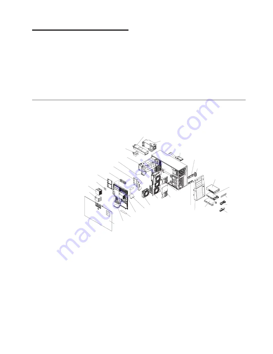
The


following


illustration


shows


the


major


components


in


the


server


(depending


on


the


server


model).


The


illustrations


in


this


document


might


differ


slightly


from


your


hardware.


Bezel

Control panel assembly

USB cable assembly

SAS/SATA
backplane

SATA
backplate

Fan

assembly

Hot-swap fan

Hot-swap power supply

Fixed power supply

Hot-swap power supply filler

Power supply cage

Hot-swap
drive

Hot-swap
drive trim piece

Simple-swap
drive

Simple-swap
drive trim piece

DVD
drive

DVD drive
trim piece

Processor baffle

ServeRAID 8k-1

VRM

Heatsink

Microprocessor

System board

Heat sink
retention bracket

Cover

Heat sink
filler

DIMMs

Drive bay EMC shield

Hard disk drive
EMC shield

DIMM air duct

Rear adapter retention bracket


©


Copyright


IBM


Corp.


2008


17

Содержание 7973

Страница 1: ...System x3400 Types 7973 7974 7975 and 7976 User s Guide...

Страница 2: ......

Страница 3: ...System x3400 Types 7973 7974 7975 and 7976 User s Guide...

Страница 4: ...age 105 and the Warranty and Support Information document on the IBM System x3400 Documentation CD Fifth Edition October 2008 Copyright International Business Machines Corporation 2008 US Government U...

Страница 5: ...s 24 Removing the bezel 25 Removing the side cover 26 Removing the front fan cage assembly 27 Installing a memory module 28 Installing a drive 34 Installing a CD or DVD drive 36 Installing a tape driv...

Страница 6: ...talling the Remote Supervisor Adapter II SlimLine firmware 91 Completing the setup 92 Using the baseboard management controller 92 Enabling and configuring SOL using the OSA SMBridge management utilit...

Страница 7: ...n tuotteen lue turvaohjeet kohdasta Safety Information Avant d installer ce produit lisez les consignes de s curit Vor der Installation dieses Produkts die Sicherheitshinweise lesen Prima di installar...

Страница 8: ...For example if a caution statement begins with a number 1 translations for that caution statement appear in the IBM Safety Information book under statement 1 Be sure to read all caution and danger st...

Страница 9: ...nt when there is evidence of fire water or structural damage v Disconnect the attached power cords telecommunications systems networks and modems before you open the device covers unless instructed ot...

Страница 10: ...um battery replace it only with the same module type made by the same manufacturer The battery contains lithium and can explode if not properly used handled or disposed of Do not v Throw or immerse in...

Страница 11: ...he device v Use of controls or adjustments or performance of procedures other than those specified herein might result in hazardous radiation exposure DANGER Some laser products contain an embedded Cl...

Страница 12: ...the device and the power switch on the power supply do not turn off the electrical current supplied to the device The device also might have more than one power cord To remove all electrical current f...

Страница 13: ...resent inside any component that has this label attached There are no serviceable parts inside these components If you suspect a problem with one of these parts contact a service technician Statement...

Страница 14: ...ed with accessories sold with this product will expose you to lead a chemical known to the State of California to cause cancer and birth defects or other reproductive harm Wash hands after handling AD...

Страница 15: ...er and basic instructions for installing some options v Warranty and Support Information This document is in Portable Document Format PDF on the IBM System x3400 Documentation CD It contains informati...

Страница 16: ...ch is on the IBM System x3400 Documentation CD Each statement is numbered for reference to the corresponding statement in the Safety Information document The following notices and statements are used...

Страница 17: ...adcom 5721 10 100 1000 Ethernet controller on the system board with RJ 45 Ethernet port v Six port Serial ATA controller v Integrated RAID capability SATA HostRAID v Remote Supervisor Adapter II SlimL...

Страница 18: ...hine Types 7975 and 7976 Depending on the server model some features might not be available or some specifications might not apply See Chapter 2 Installing options on page 17 for more detail informati...

Страница 19: ...in v Weight 20 kg 42 lb to 34 kg 75 lb depending upon configuration Integrated functions v Baseboard management controller BMC or onboard service processor v Broadcom 5721 10 100 1000 Ethernet contro...

Страница 20: ...stalled hardware options and provides the correct configuration programs and device drivers For more information about the ServerGuide Setup and Installation CD see Using the ServerGuide Setup and Ins...

Страница 21: ...e performance of the server v Systems management capabilities The server supports an optional Remote Supervisor Adapter II SlimLine which provides service processor functions in addition to those that...

Страница 22: ...or log v Baseboard management controller BMC or service processor v Power management v Power on self test POST v Read only memory ROM checksums v Redundant Ethernet capabilities requires an optional E...

Страница 23: ...esktop computers workstations and mobile computers v Support for systems management industry standards v Integration into leading workgroup and enterprise systems management environments v Ease of use...

Страница 24: ...s LEDs and connectors on the front of the hot swap server models USB connectors Power control button Front information panel CD or DVD eject button CD or DVD drive activity LED green System power LED...

Страница 25: ...esent or the power supply or the LED itself has failed Power control button Press this button to turn the server on and off manually Hard disk drive activity LED When this LED is flashing rapidly it i...

Страница 26: ...t board behind drive bays 4 through 7 Hot swap hard disk drive status LED some models On some server models each hot swap hard disk drive has an amber status LED If this amber status LED is lit it ind...

Страница 27: ...ouse Keyboard Serial 1 COM 1 Video Parallel USB 4 RJ45 Ethernet 10 100 1000 RJ45 Ethernet 10 100 for Remote Supervisor Adapter II SlimLine USB 3 NMI button AC power LEDs DCpower LEDs Power cords Seria...

Страница 28: ...nector Video connector Connect a monitor to this connector USB connectors Connect USB devices to these connectors Ethernet connector Use this connector to connect the server to a network Serial 2 conn...

Страница 29: ...server can also be turned on in any of the following ways v If a power failure occurs while the server is turned on the server will restart automatically when power is restored v If your operating sy...

Страница 30: ...the device ensure that all power cords are disconnected from the power source 1 2 The server can be turned off in any of the following ways v You can turn off the server from the operating system if...

Страница 31: ...e server Server components The following illustration shows the major components in the server depending on the server model The illustrations in this document might differ slightly from your hardware...

Страница 32: ...r Power Front panel USB tape Primary IDE Front USB Microprocessor 1 Microprocessor 2 SAS SATA backplane 1 power Simple swap SATA backplate SAS SATA backplane 2 power Hot swap SAS SATA 1 signal Hot swa...

Страница 33: ...number Description 1 Boot block v When this switch is on 1 this is normal mode v When this switch is toggled to On this enables the system to recover if the BIOS code becomes damaged See the Problem...

Страница 34: ...onnectors on the system board Mouse Keyboard Serial 1 COM 1 Parallel Video USB 4 RJ45 Ethernet 10 100 1000 RJ45 Ethernet 10 100 for Remote Supervisor Adapter II SlimLine USB 3 NMI button Serial 2 COM...

Страница 35: ...System board option connectors The following illustration shows the system board connectors for user installable options Chapter 2 Installing options 21...

Страница 36: ...tive devices on page 24 This information will help you work safely v Before you install optional hardware make sure that the server is working correctly Start the server and make sure that the operati...

Страница 37: ...you might find it easier to lay the server on its side v When you are finished working on the server reinstall all safety shields guards labels and ground wires v For a list of supported options for t...

Страница 38: ...bserve the following precautions v Limit your movement Movement can cause static electricity to build up around you v The use of a grounding system is recommended For example wear an electrostatic dis...

Страница 39: ...st unlock the side cover to remove the bezel 3 Position your finger on the depressed area on the left side of the bezel and rotate the bezel away from the server 4 Press the retention tabs on the hing...

Страница 40: ...er side cover complete the following steps 1 Read the safety information that begins on page v and Installation guidelines on page 22 2 Turn off the server and all attached devices see Turning off the...

Страница 41: ...wn on the orange release lever and pull the power supply out of the bay using the handle b Lift up the power supply cage handle and pull the power supply cage assembly all the way up until the retaine...

Страница 42: ...t are organized into two branches Each branch has two channels and each channel controls two DIMMs DIMMs that are next to each other for example DIMM slot 1 and DIMM slot 4 within the channels of a br...

Страница 43: ...y disables a failed rank pair of DIMMs from the system configuration and activates an online spare rank pair of DIMMs to replace the failed rank pair of DIMMs For an online space pair of DIMMs to be a...

Страница 44: ...certain amount of memory must be reserved for system resources To view the total amount of installed memory and the amount of configured memory run the Configuration Setup Utility program and select...

Страница 45: ...e the hot swap power supply Press down on the orange release lever and pull the power supply out of the bay using the handle b Lift up the power supply cage handle and pull the power supply cage assem...

Страница 46: ...he slots at the ends of the DIMM connector Firmly press the DIMM straight down into the connector by applying pressure on both ends of the DIMM simultaneously The retaining clips snap into the locked...

Страница 47: ...he power supply cage assembly into the chassis Power supply support bracket Power supply release tab 12 If you have a hot swap model reinstall the hot swap power supplies If you have other options to...

Страница 48: ...server and the location of the drive bays Your hardware might differ depending on the model The following is an illustration of the hot swap server models Bay 1 Bay 2 Bay 3 Bay 4 Bay 5 Bay 6 Bay 7 Ba...

Страница 49: ...rives and DVD CD RW combo drives are examples of removable media drives You can install removable media drives only in bays 1 2 and 3 v To install a 3 5 in drive in a 5 25 in bay you must use a 5 25 i...

Страница 50: ...cover see Removing the side cover on page 26 5 Place your finger on the depression area on the left side of the bezel door and rotate it away from the server After you rotate the bezel beyond 90 pull...

Страница 51: ...Laser Product Laser Klasse 1 Laser Klass 1 Luokan 1 Laserlaite Appareil A Laser de Classe 1 7 Rotate the power supply cage assembly out of the chassis v Hot swap models a Remove the hot swap power sup...

Страница 52: ...ou are installing a 3 5 in drive in bay 2 attach the 5 25 in conversion kit and push the drive into the drive bay 13 Connect one end of the signal cable to the rear of the drive and make sure that the...

Страница 53: ...following steps 1 Read the safety information that begins on page v and Installation guidelines on page 22 2 Turn off the server and peripheral devices and disconnect the power cords and all external...

Страница 54: ...y unpainted metal surface on the server then remove the tape drive from the package and place it on a static protective surface 10 Slide the tape drive into the server from the front of the drive cage...

Страница 55: ...e dust shield and pull it out of the signal connector v To maintain proper system cooling do not operate the server for more than 10 minutes without either a drive or a filler panel installed in each...

Страница 56: ...er is configured for RAID operation using an optional ServeRAID adapter you might have to reconfigure your disk arrays after installing hard disk drives See the ServeRAID documentation on the IBM Serv...

Страница 57: ...22 2 Turn off the server and peripheral devices and disconnect all external cables and power cords 3 Unlock the side cover 4 Remove the side cover see Removing the side cover on page 26 5 Place your...

Страница 58: ...ts the IDs for the hard disk drives and backplate that are connected to simple swap models Device ID Drive bay 4 3 Drive bay 5 2 Drive bay 6 1 Drive bay 7 0 Power and signal cables for internal drives...

Страница 59: ...k drive signal cable to a different connector on the system board and connect a RAID level 5 Enabler plug to the system board See Installing the ServeRAID 8k adapter on page 57 for information on how...

Страница 60: ...f you install an x8 adapter in slot 1 that can downshift to the x4 bandwidth it will run at the x4 bandwidth The x8 connector can be used for x4 and x8 adapters Check the information that comes with y...

Страница 61: ...on the right side of the front adapter retention bracket to release the retaining tab on the left side of the bracket 6 Remove the screw that secures the expansion slot cover to the chassis Store the...

Страница 62: ...h one microprocessor installed but supports up to two microprocessors Note A microprocessor must be installed and removed only by a trained service technician v Read the documentation that comes with...

Страница 63: ...r and pull the power supply out of the bay using the handle b Lift up the power supply cage handle and pull the power supply cage assembly all the way up until the retainer latch locks the cage in pla...

Страница 64: ...d Align the microprocessor with the socket note the alignment mark and the position of the notches then carefully place the microprocessor on the socket and close the microprocessor bracket frame Mic...

Страница 65: ...essor 2 Microprocessor release lever Microprocessor 2 VRM d Slide the flange of the heat sink into the opening beneath the retainer bracket Heat sink locking lever Heat sink Microprocessor Chapter 2 I...

Страница 66: ...ver comes with one power supply v The redundant mode requires two 835 watt hot swap power supplies in the server You must install an additional redundant power and cooling option kit the option kit co...

Страница 67: ...that is released to internal server components when the server is powered on might cause the server to halt which could result in the loss of data To avoid this potential problem always use an electr...

Страница 68: ...he power supply from the package and place it on a static protective surface 6 Place the power supply into the bay guides Power supply filler Release latch Power supply 7 Press down on the orange rele...

Страница 69: ...atic discharge wrist strap or other grounding system when working inside the server with the power on 2 Remove the side cover see Removing the side cover on page 26 Attention To ensure proper system c...

Страница 70: ...he ServeRAID 8k l adapter complete the following steps 1 Read the safety information beginning on page v and Installation guidelines on page 22 2 Turn off the server and peripheral devices and disconn...

Страница 71: ...required However if you install this optional ServeRAID 8k adapter in simple swap SATA models see the following instructions for cabling information To install the ServeRAID 8k adapter complete the fo...

Страница 72: ...e to the system board or the ServeRAID 8k adapter ServeRAID 8k connector ServeRAID 8k adapter 7 Press the ServeRAID 8k adapter firmly into the connector 8 Mount the battery pack to the chassis using t...

Страница 73: ...rnal connectors on page 18 for the location of these connectors on the system board Note Remove the dust shield if one is present from the Hot swap SAS SATA 1 signal connector on the system board befo...

Страница 74: ...ller The optional IBM ServeRAID MR10is VAULT SAS SATA controller can be installed only in its dedicated PCI slot 2 connector on the system board and only in server models with eight 3 5 inch hot swap...

Страница 75: ...re the expansion slot cover and screw in a safe place for future use Note Expansion slot covers must be installed on all vacant slots This maintains the electronic emissions standards of the server an...

Страница 76: ...se lever and pull the power supply out of the bay using the handle b Lift up the power supply cage handle and pull the power supply cage assembly all the way up until the retainer latch locks the cage...

Страница 77: ...the connectors on the controller to which you connect the signal cables from the drive backplanes The following illustration shows which end of the cable connects to the backplane and to the controlle...

Страница 78: ...e the cable around the right side of the front fan cage assembly and along the chassis wall make sure that the cable is in front of the fan cage release tab then connect it to connector J8 on the Serv...

Страница 79: ...ms management Ethernet port on the rear of the server is active To install a Remote Supervisor Adapter II SlimLine complete the following steps 1 Read the safety information beginning on page v and In...

Страница 80: ...grasp the Remote Supervisor Adapter II SlimLine by its top edge or upper corners and align it with the Remote Supervisor Adapter II SlimLine guide and the connector on the system board Attention Incom...

Страница 81: ...ess the Remote Supervisor Adapter II SlimLine firmly into the connector and under the retention clip on the Remote Supervisor Adapter II SlimLine support bracket 9 Close the rear adapter retention bra...

Страница 82: ...he bezel complete the following steps 1 Align the hinge assembly with the hinge holes on the chassis Bezel Retention tabs Hinge assembly 2 Push the hinges into the holes on the chassis until they snap...

Страница 83: ...it in place Sliding hinge mount Hinge assembly Hinge pin b Align the sliding hinge mount with the hinge pin on the hinge assembly on the chassis c Press the sliding hinge mount against the hinge pin...

Страница 84: ...nstalled and seated correctly and that you have not left loose tools or parts inside the server Also make sure that all internal cables are correctly routed 2 Insert the bottom edges of the cover into...

Страница 85: ...nector and so on The following illustration shows the input output I O connectors on the rear of the hot swap power supply models with optional redundant power Mouse Keyboard Serial 1 COM 1 Video Para...

Страница 86: ...erveRAID adapter and you have installed or removed a hard disk drive see the ServeRAID documentation that comes with the server for information about reconfiguring the disk arrays If you have installe...

Страница 87: ...om a tower model to a rack model you must use a Tower to Rack Kit You can then install the server in a rack cabinet To order a Tower to Rack Kit for the server contact your IBM marketing representativ...

Страница 88: ...74 System x3400 Types 7973 7974 7975 and 7976 User s Guide...

Страница 89: ...rtable device and you can customize where the network startup option appears in your startup sequence Enable the Broadcom Gigabit Ethernet Utility from the Configuration Setup Utility program For info...

Страница 90: ...ettings for the baseboard management controller BMC v View and clear error logs Starting the Configuration Setup Utility program To start the Configuration Setup Utility program complete the following...

Страница 91: ...al remote video and keyboard redirection and to set other remote console values This choice is on the full Configuration Setup Utility menu only Parallel Port Setup Select this choice to enable or dis...

Страница 92: ...adapter has boot precedence If you enable the boot fail count the BIOS default settings will be restored after three consecutive failures to find a boot record v Advanced Setup Select this choice to...

Страница 93: ...eboard management controller BMC network configuration information NMI Options Select this choice to enable or disable the NMI reboot Enabled is the default v Error Logs Select this choice to view or...

Страница 94: ...authority to set change and delete the power on password A user who types the power on password has access to only the limited Configuration Setup Utility menu the user can set change and delete the p...

Страница 95: ...t Web site at http www ibm com servers eserver xseries systems_management sys_migration serverguide sub html The ServerGuide program has the following features v An easy to use interface v Diskette fr...

Страница 96: ...e device drivers that are required for your hardware and for the operating system that you are installing This section describes a typical ServerGuide operating system installation Note Features and f...

Страница 97: ...Enter 2 Select Planar Ethernet and use the Right Arrow key to set it to Enabled 3 Select Save Settings and press Enter Configuring the Broadcom Gigabit Ethernet controller The Ethernet controller is i...

Страница 98: ...table exe file to download the file and follow the instructions in the readme file to install the update or interim fix h Repeat steps 3f and 3g for any additional updates or interim fixes that you wa...

Страница 99: ...ls 0 1 5 6 10 50 and 60 You can install the ServeRAID MR10is SAS SATA controller only in server models with eight 3 5 inch hot swap hard disk drives installed For instructions on how to install the Se...

Страница 100: ...Disk Utilities Select this choice to format a disk or verify the disk media Select a device from the list and read the instructions on the screen carefully before making a selection Starting IBM Serv...

Страница 101: ...ial ATA SATA controller To enable the SATA RAID controller complete the following steps 1 Turn on the server 2 When the prompt Press F1 for Configuration Setup appears press F1 If you have set an admi...

Страница 102: ...to group into the array 5 When you are prompted to select the RAID level select RAID 0 or RAID 1 6 Optional Type an identifier for the array 7 When you are prompted for the array build method select Q...

Страница 103: ...ServeRAID Manager in Startable CD mode To run ServeRAID Manager in Startable CD mode turn on the server then insert the IBM ServeRAID Support CD into the CD or DVD drive If ServeRAID Manager detects a...

Страница 104: ...bject appears in the right pane To display a list of available actions for an object click the object and click Actions Remote Supervisor Adapter II SlimLine You can use an optional Remote Supervisor...

Страница 105: ...nnector 2 Connect the other end of the cable to the network Installing the Remote Supervisor Adapter II SlimLine firmware The software and firmware files that you need are contained in one system serv...

Страница 106: ...tem components fail the baseboard management controller lights LEDs to help you diagnose the problem and also records the error in the System Event Error log The baseboard management controller also p...

Страница 107: ...gher v Remote Console Connection Type VT100 v Remote Console Connect Direct v Remote Console Flow Control Hardware v Remote Console Active After Boot Enabled d Press Esc twice to exit the Remote Conso...

Страница 108: ...e to enable a user to log in as the root user through the SOL console ttyS0 LILO configuration If you are using LILO complete the following steps 1 Complete the following steps to modify the etc lilo...

Страница 109: ...nstall boot boot b message boot message linear image boot vmlinuz 2 4 9 e 12smp label linux initrd boot initrd 2 4 9 e 12smp img read only root dev hda6 image boot vmlinuz 2 4 9 e 12 label linux up in...

Страница 110: ...ating system starts a LILO boot prompt is displayed instead of the graphical user interface Press Tab at this prompt to install all of the boot options that are listed To load the operating system in...

Страница 111: ...ed by anaconda Note that you do not have to rerun grub after making changes to this file NOTICE You have a boot partition This means that all kernel and initrd paths are relative to boot eg root hd0 0...

Страница 112: ...2 4 9 e 12 img You must restart the Linux operating system after completing these procedures for the changes to take effect and to enable SOL SUSE SLES 8 0 configuration Note This procedure is based...

Страница 113: ...olor white blue black light gray default 0 timeout 8 title linux kernel hd0 1 boot vmlinuz root dev hda2 acpi oldboot vga 791 1 initrd hd0 1 boot initrd title floppy root chainloader 1 title failsafe...

Страница 114: ...ess Enter to display the current boot options for your server b In the Boot Entries section locate the boot entry ID for the section with an OS friendly name of Windows Server 2003 Standard Write down...

Страница 115: ...i 0 disk 0 rdisk 0 partition 1 WINDOWS OS Load Options fastdetect redirect You must restart the Windows 2003 operating system after completing this procedure for the changes to take effect and to enab...

Страница 116: ...Go to http www ibm com support and download the utility program and create the OSA BMC Management Utility CD 2 Insert the OSA BMC Management Utility CD into the drive 3 Type mount mnt cdrom 4 Locate t...

Страница 117: ...baseboard management controller firmware and SDR FRU data The firmware update utility updates the baseboard management controller firmware and SDR FRU data only and does not affect any device drivers...

Страница 118: ...ccess the SOL network Type help at the smbridge prompt for more information Use the following commands in an SOL session connect Connect to the LAN Type connect ip ip_address u username p password ide...

Страница 119: ...or implied warranties in certain transactions therefore this statement may not apply to you This information could include technical inaccuracies or typographical errors Changes are periodically made...

Страница 120: ...CD or DVD drive speed is the variable read rate Actual speeds vary and are often less than the possible maximum When referring to processor storage real and virtual storage or channel volume KB stand...

Страница 121: ...ie de programas y servicios de devoluci n de productos en varios pa ses a fin de ayudar a los propietarios de equipos a reciclar sus productos de TI Se puede encontrar informaci n sobre las ofertas de...

Страница 122: ...service manual for specific battery information The battery must be recycled or disposed of properly Recycling facilities may not be available in your area For information on disposal of batteries ou...

Страница 123: ...ccumulators Customer participation is important to minimize any potential effects of batteries and accumulators on the environment and human health due to the potential presence of hazardous substance...

Страница 124: ...y cause radio interference in which case the user may be required to take adequate measures United Kingdom telecommunications safety requirement Notice to Customers This apparatus is approved under ap...

Страница 125: ...0049 0 711 785 1283 E mail tjahn de ibm com Taiwanese Class A warning statement Chinese Class A warning statement Japanese Voluntary Control Council for Interference VCCI statement Korean Class A warn...

Страница 126: ...112 System x3400 Types 7973 7974 7975 and 7976 User s Guide...

Страница 127: ...Ethernet Utility enabling 83 general information 75 C cables internal drives 44 power 44 cables continued rear connectors 71 signal 44 cabling hot swap SAS drives 45 hot swap SATA drives 45 Simple swa...

Страница 128: ...agnetic compatibility EMC shield 36 electronic emission Class A notice 109 EMC shield hard disk drive bay 36 41 enabling Broadcom Gigabit Ethernet Utility 83 controllers 77 Serial ATA RAID feature 87...

Страница 129: ...r 57 the ServeRAID MR10is adapter 60 installing memory sequence for mirrored mode 29 installing the server in a Tower to Rack Kit 73 integrated network support 6 integrated SATA controller enabling 87...

Страница 130: ...word 80 power on self test POST error log 79 processor control 78 product recycling and disposal 107 R RAID array Serial ATA creating 88 RAS features 7 RAS See also features reliability availability a...

Страница 131: ...arting the Setup and Installation CD 82 using 81 serviceability features 7 setup advanced 78 Configuration Setup Utility 76 with ServerGuide 82 simple swap drives 43 Simple swap SATA drives cabling 45...

Страница 132: ...eboard management controller utility programs 92 the IBM ServeRAID Configuration Utility program 86 the RAID configuration programs 84 utility Array Configuration 87 Configuration Setup 76 Ethernet 75...

Страница 133: ......

Страница 134: ...Part Number 44W2584 Printed in USA 1P P N 44W2584...

Отзывы: