9.
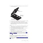
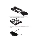
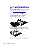
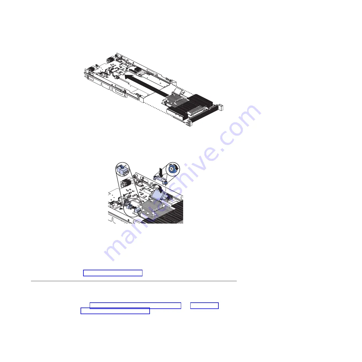
Carefully reposition the expansion-unit riser assembly, aligning it with the
expansion-unit system-board-assembly rails.
10.
Firmly slide the assemblies together until the tray-release button securely
locks the panels.
11.
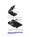
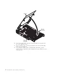
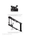
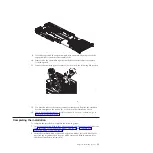
Connect the auxiliary power cable (A), as shown in the following illustration.
A
B
12.
Connect the cable to the expansion-unit system board. Replace the retention
bracket and tighten the screws (B), as shown in the illustration above.
13.
If you have other devices to install or remove, do so now; otherwise, go to
“Completing the installation.”
Completing the installation
To complete the installation, complete the following steps:
1.
Install any expansion blades that were removed and the expansion blade cover
(see “Installing a GPU Expansion Blade” on page 8 and “Installing the
expansion blade cover” on page 15).
2.
Insert the combined blade server and expansion blades into the BladeCenter
unit (see the documentation for your blade server and BladeCenter unit for
additional installation information).
Chapter 3. Installing options
21
Содержание 68Y7493
Страница 1: ...BladeCenter GPU Expansion Blade Installation Guide ...
Страница 2: ......
Страница 3: ...BladeCenter GPU Expansion Blade Installation Guide ...
Страница 6: ...iv BladeCenter GPU Expansion Blade Installation Guide ...
Страница 16: ...xiv BladeCenter GPU Expansion Blade Installation Guide ...
Страница 20: ...4 BladeCenter GPU Expansion Blade Installation Guide ...
Страница 22: ...6 BladeCenter GPU Expansion Blade Installation Guide ...
Страница 42: ...26 BladeCenter GPU Expansion Blade Installation Guide ...
Страница 46: ...30 BladeCenter GPU Expansion Blade Installation Guide ...
Страница 54: ...38 BladeCenter GPU Expansion Blade Installation Guide ...
Страница 57: ......
Страница 58: ... Part Number 90Y5467 Printed in USA 1P P N 90Y5467 ...

