


The power that is used by the system depends on various factors, including the number of enclosures and
drives in the system and the ambient temperature.
Note: The data in Table 12 on page 43 measurements are presented as an example. Measurements that
are obtained in other operating environments might vary. Conduct your own testing to determine specific
measurements for your environment.
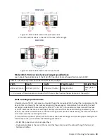
Each utility node enclosure contains two PSUs for redundancy. The total power consumption values
represent the total power that is drawn by both PSUs when operating together or a single PSU when
operating in a maintenance or failure mode.
Note: The base system may be shipped without the power supply. Users must install the original or same
model of power supplies; FSP Group Inc, FSP2000-20HM is to be used with the utility node (MTM 5149 -
23E) to be able to operate it.
Environmental requirements
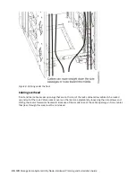
System airflow is from the front to the rear of each enclosure:
• Airflow passes between drive carriers and through each enclosure.
• The combined power and cooling module exhausts air from the rear of each canister.
Ensure that your environment falls within the ranges that are listed in the following table.
Table 13. Temperature requirements for the utility node
Environment
Ambient temperature
Altitude
Relative humidity
Operating
10°C to 35°C
1
(50°F to 95°F)
-61 to 3048 m
2, 3
(-200 to 10000 ft)
20% to 80%
noncondensing
Non-operating
- 40°C to 70°C
(-40°F to 158°F)
10% to 90%
noncondensing
Transit
-40°C to 60°C
(-40°F to 140°F)
-61 to 12192 m
(-200 to 40000 ft)
10% to 90%
noncondensing
Note:
• Max ambient temperature environment = 32°C / 950 m
• Max altitude environment = 25°C / 3050 m
• Decrease the maximum air temperature by 1°C per 300 m above 950 m.
• The maximum ambient operating temperature when using an optical cable or discrete optical
transceiver is 32°C, which includes all Ethernet (100 Gb) cables and InfiniBand (100 Gb EDR) that
are greater than or equal to 3 m in length.
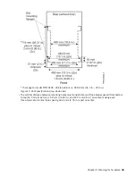
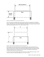
Dimensions and weight requirements for rack installation
Ensure that space is available in a standard 19 in. rack that is capable of supporting the system. The rack
rail kit supports racks with threaded round and square rail mounting holes. The following table lists the
dimensions and weights of the server.
Table 14. Physical characteristics of the utility node
Server
Height
Width
Depth
Maximum weight
IBM Storage
Scale System Utility
Node
87 mm
(3.43 in.)
438.4 mm
(17.26 in.)
640 mm
(25 in.)
25 kg (55 lb)
44 IBM Storage Scale System Utility Node: Hardware Planning and Installation Guide
Содержание 6.1.8.2
Страница 8: ...viii...
Страница 20: ...xx IBM Storage Scale System Utility Node Hardware Planning and Installation Guide...
Страница 90: ...70 IBM Storage Scale System Utility Node Hardware Planning and Installation Guide...
Страница 96: ...76 IBM Storage Scale System Utility Node Hardware Planning and Installation Guide...
Страница 100: ...80 IBM Storage Scale System Utility Node Hardware Planning and Installation Guide...
Страница 102: ...82 IBM Storage Scale System Utility Node Hardware Planning and Installation Guide...
Страница 110: ...90 IBM Storage Scale System Utility Node Hardware Planning and Installation Guide...
Страница 112: ...92 IBM Storage Scale System Utility Node Hardware Planning and Installation Guide...
Страница 113: ......
Страница 114: ...IBM Product Number 5765 DME 5765 DAE SC28 3469 00...