background image

Содержание 5280

Страница 1: ..._ GA21 9365 Q 5280 00 IBM 5280 Distributed Data System User s Setup Procedures...

Страница 2: ...country Publications are not stocked at the address below Requests for copies of IBM publications and for technical information about the system should be made to your IBM representative or to the bra...

Страница 3: ...es after you have set them up Section 9 presents the procedures for connecting the communications lines to the 5280 system Section 10 provides general instructions for disconnecting and relocating you...

Страница 4: ...iv...

Страница 5: ...7 BASIC OPERATIONAL INFORMATION 88 Keyboards 88 Displays 89 Diskettes 91 Diskette Drives 92 SYSTEM CHECKOUT PROCEDURE 94 Diskette 1 Drive System Checkout Procedure 106 Diskette 2D Drive System Checkou...

Страница 6: ...vi...

Страница 7: ...number to each keyboard on the setup form Placed each device where it will be set up If you have communications the following must also have been completed Installed communications equipment Completed...

Страница 8: ...ct your supervisor The cables and cable connectors are durable but can be damaged if thrown or stepped on Before you begin a setup procedure look at the machine number on the device The machine number...

Страница 9: ...Safety Precaution A 5280 device can weigh up to 90 kilograms 200 pounds NEVER LIFT A DEVICE BY YOURSELF User s Setup Procedures 3...

Страница 10: ...4...

Страница 11: ...p Procedure Safety Precaution This device weighs approximately 68 kilograms 150 pounds NEVER LIFT IT BY YOURSELF 1 Place the keyboard to the left of the display screen Keyboard Machine Number _ User s...

Страница 12: ...nnect the keyboard cable by positioning the connector so that the IBM logo is up and then push the connector into the socket 11 I1 cst J l Juow oW IBM Logo 3 Make sure that the snap locks lock into po...

Страница 13: ...magnetic stripe reader taped to the top of your data station Magnetic Stri pe Reader 5 If you have a magnetic stripe reader remove unwrap and place the reader beside the keyboard Magnetic Stripe Read...

Страница 14: ...8 6 If you have a diskette drive s open the diskette locking lever s 7 Make sure that the Power switch is set to the 0 Off position...

Страница 15: ...e diskette drive cable optional Note The cables do not carry high voltage There is no danger of electrical shock Each cable connector is color coded The data station cable connector is color coded gre...

Страница 16: ...111111111111111111111111111111111111111111 1111111111111111111111111 11 111111 11111111111111111 Green Label yellow Label L n In addition to the color coded connectors and sockets there should be iden...

Страница 17: ...you will connect the data station cable Yellow Label_II Green Label II Back View of the 5281 b Find a cable connector with a green label Read the identification label to be sure that it connects to 52...

Страница 18: ...p 11 10 Read the following four steps a b c and d before connecting the diskette drive cable a Look at the diskette drive socket with the yellow label This is where you will connect the diskette drive...

Страница 19: ...push the cable end into the socket make sure that the colors match d Make sure that the snap locks lock into position 11 Cut and remove the string from the power cord plug 12 Insert the power cord pl...

Страница 20: ...ntification tabs except for the first tab in the following manner Note Depending on the binder you may only have two tabs to insert MANUAL NAME MANUAL NAME First Tab MANUAL NAME c Insert the tabs into...

Страница 21: ...he printer s using the customer setup manual that came with the printer Do not connect the printer cable s The printer cable s will be connected using this manual When you have completed the setup pro...

Страница 22: ...16...

Страница 23: ...cedure Safety Precaution This device weighs approximately 68 kilograms 150 pounds NEVER LIFT IT BY YOURSELF Machine Number _ 5282 1 Find the keyboards and place them in front of the display screens Us...

Страница 24: ...k to see if you have a magnetic stripe reader in each of 1 he mirror housings on the 5282 3 If you have magnetic stripe readers remove unwrap and place the readers beside the keyboards I Magnetic Stri...

Страница 25: ...e mirrors are smudged clean the mirrors with glass cleaner Mirrors 5 Insert a mirror on each side of the display screen as follows Lay the mirror on the top or bottom ledge of the mirror housing then...

Страница 26: ...6 Do the following a Open the diskette locking lever s b Make sure that the Power switch is set to the 0 Off position 20...

Страница 27: ...7 Remove the access cover by pressing down with your thumb and pulling out Side View I Cable Access Cover User s Setup Procedures 21...

Страница 28: ...yboard cables to the cable sockets a Push in the left keyboard cable with the IBM logo facing to the right i Left Cable Socket b Push in the right keyboard cable with the IBM logo facing to the right...

Страница 29: ...e If the cable does not fit easily into the socket be sure that the connector guides line up with the socket guides 9 Make sure that the snap locks lock into position Snap Lock User s Setup Procedures...

Страница 30: ...high voltage There is no danger of electrical shock Each cable connector is color coded The data station cable connector is color coded green The diskette drive cable is color coded yellow Green or Ye...

Страница 31: ...d Site Prepartion Guide The label identifies which device the cable connects to 10 Read the following four steps a b c and d before connecting the data station cable a Look at the data station socket...

Страница 32: ...the 5282 c Position the cable so that the green label is on top then push the cable end into the socket make sure that the colors match Note If the cable does not fit easily into the socket be sure t...

Страница 33: ...b c and d before connecting the diskette drive cable a Look at the diskette drive socket with the yellow label This is where you will connect the diskette drive cable b Find a cable connector with a y...

Страница 34: ...e cable end does not fit easily into the socket be sure that the connector guides line up with the socket guides d Make sure that the snap locks lock into position 13 Replace the cable access cover 14...

Страница 35: ...except for the first tab in the following manner Note Depending on the binder you may only have two tabs to insert MANUAL NAME MANUAL NAME First Tab MANUAL NAME c Insert the tabs into the plastic cov...

Страница 36: ...5288 Go set up the printer s using the customer setup manual that came with the printer Do not connect the printer cable s The printer cable s will be connected using this manual When you have complet...

Страница 37: ...cedure Safety Precaution This device weighs approximately 68 kilograms 150 pounds NEVER LIFT IT BY YOURSELF Machine Number _ 5286 1 Find the keyboards and place them in front of the display screens Us...

Страница 38: ...32 2 Check to see if you have a magnetic stripe reader in each of the mirror housings on the 5286 3 If you have magnetic stripe readers remove unwrap and place the readers beside the keyboards...

Страница 39: ...e mirrors are smudged clean the mirrors with glass cleaner Mirrors 5 Insert a mirror on each side of the display screen as follows Lay the mirror on the top or bottom ledge of the mirror housing then...

Страница 40: ...6 Do the following a Open the diskette locking lever s b Make sure that the Power switch is set to the a Off position 34...

Страница 41: ...the Keylock feature are packaged in the customer setup envelope The envelope looks like this b Record the identification number of the keys c Insert the key and turn it to the right If the key does n...

Страница 42: ...36 8 Remove the access cover by pressing down with YOur thumbJ and pulling out I...

Страница 43: ...cables to the cable socket a Push in the left keyboard cable with the IBM logo facing to the right I I Left Cable Socket b Push in the right keyboard cable with the IBM logo facing to the right User...

Страница 44: ...38 Note If the cable does not fit easily into the socket be sure that the connector guides line up with the socket guides 10 Make sure that the snap locks lock into position Snap Lock II Snap Lock...

Страница 45: ...e The cables do not carry high voltage There is no danger of electrical shock Each cable connector is color coded The data station cable connector is color coded green The diskette drive cable is colo...

Страница 46: ...0 In addition to the color coded connectors and sockets there should be identification labels If not see the Planning and Site Preparation Guide The label identifies which device the cable connects to...

Страница 47: ...bel This is where you will connect the data station cable from an auxiliary device b Find a cable connector with a green label c Position the cable so that the green label is on top then push the cabl...

Страница 48: ...diskette drive cable a Look at the diskette drive socket with the yellow label This is where you will connect the diskette drive cable SJ b Find a cable connector with a yellow label c Position the ca...

Страница 49: ...13 Replace the cable access cover 14 Cut and remove the string from the power cord plug 15 Insert the power cord plug into a grounded receptacle User s Setup Procedures 43...

Страница 50: ...tab in the following manner Note Depending on the binder you may only have two tabs to insert MANUAL NAME MANUAL NAME First Tab MANUAL NAME c Insert the tabs into the plastic cover found on the binder...

Страница 51: ...p Procedure Safety Precaution This device weighs approximately 68 kilograms 150 pounds NEVER LIFT IT BY YOURSELF 1 Place the keyboard to the left of the display screen Machine Number _ 5285 _ User s S...

Страница 52: ...46 2 Connect the keyboard cable by positioning the connector so that the IBM logo is up and then push the connector into the socket 11 11 0 JJ rfJ J UoW oW...

Страница 53: ...position 4 Check to see if you have a magnetic stripe reader taped to the top of your data station If you have a magnetic stripe reader remove unwrap and place the reader beside the keyboard Magnetic...

Страница 54: ...48 5 If you have a diskette drivels open the diskette locking levtlr s 6 Make sure that the Power switch is set to the 0 Off position...

Страница 55: ...ep 8 a The keys for the Keylock feature are packaged in the customer setup envelope The envelope looks like this b Record the identification number of the keys c Insert a key and turn it to the right...

Страница 56: ...coded The data station cable connector is color coded green The diskette drive cable is color coded yellow Green or YeIlow Label Each socket is also color coded The data station socket is color coded...

Страница 57: ...In addition to the color coded connectors and sockets there are identification labels The label identifies which device the cable connects to User s Setup Procedures 51...

Страница 58: ...he data station socket with the green label This is where you will connect the data station cable from an auxiliary device Data Station Socket Green Label b Find a cable connector with a green label c...

Страница 59: ...have trouble pushing in the cable make sure that the connector guides line up with the socket guides Guides Connector Guides d Make sure that the snap locks lock into position Snap Lock User s Setup P...

Страница 60: ...following four steps a b c and d before connecting the diskette drive cable a Look at the diskette drive socket with the yellow label This is where you will connect the diskette drive cable from an a...

Страница 61: ...r left then push the cable end into the socket Note If you have trouble pushing the connector into the socket make sure that the connector guides line up with the socket guides d Make sure that the sn...

Страница 62: ...step 13 a Look at the printer socket Number 20J I I _ 11111111111111111111111111111111111111111111111111111 111111111111111111111111111111111111111 II III III Back View b Find the printer cable c Lin...

Страница 63: ...tor into the socket and turn the retaining ring clockwise until the ring is tight Socket 1 e Go to the printer and look at the access panel on the back of the printer Access Panel 5256 or 5225 User s...

Страница 64: ...ljPrinter SoCket k input 5256 5225 Note If the printer access panel has the Terminator and Address switches connect the cable and set the switches as shown in the following example From 5285 13 If you...

Страница 65: ...the cable into the socket Socket Guide Connector Guide Note If the cable does not fit easily into the socket make sure that the connector guides line up with the socket guides d Make sure that the sn...

Страница 66: ...er of each manual b Fold the identification tabs except for the first tab in the following manner Note Depending on the binder you may only have two tabs to insert MANUAL NAME MANUAL NAME ry First Tab...

Страница 67: ...ocedure Safety Precaution This device weighs approximately 90 kilograms 200 pounds NEVER ATTEMPT TO LIFT IT BY YOURSELF Machine Number _ 5288 1 Do the following a Open the diskette locking levers User...

Страница 68: ...62 b Make sure that the Power switch is set to the 0 Off position IIIIIIIIIII1I 2 If your device has the Keylock feature read and do the following If not go to step 4 Keylock...

Страница 69: ...re packaged in the customer setup envelope The envelope looks like this b Record the idendification number of the keys 3 Insert a key and turn it to the right If it does not turn to the right use the...

Страница 70: ...ou are connecting a 5282 data station cable with two keyboards to socket 0 1 In this procedure you will be connecting several cables The cables are Up to four data station cables colored coded green U...

Страница 71: ...ts to socket 0 on the 5288 Data Station ca ble Machine Type XXXX Location Socket JL From the 5281 or 5282 To Socket 0 on the 5288 b Position the cable so that the green label is on top then push the c...

Страница 72: ...ough 13 11111111111111111111 7 If you do not have a diskette drive cable s to attach to the 5288 go to step 9 If you do read and do the following four steps before connecting the cable a Find a cable...

Страница 73: ...he cable end does not fit easily into the socket be sure that the connector guides line up with the socket guides c Make sure that the snap locks lock into position d Repeat this procedure for the rem...

Страница 74: ...socket number 20 21 22 and 23 This is where you will connect the printer cable s 111111111111111111 b Find the printer cable and look at the label Read the label to determine which socket to connect t...

Страница 75: ...d Insert the connector into the socket and turn the retaining ring clockwise until the ring is tight e If you have more than one printer to attach repeat this procedure User s Setup Procedures 69...

Страница 76: ...0 9 Go to the printer and look at the access panel on the back of the printer Access Panel 5256 or 5225 10 If your printer has two sockets and several switches as shown below go to step 13 OR 4 I 5225...

Страница 77: ...attach go back to step 9 If not answer the following Do you have communications l Yes No Go to step 22 Go to step 21 13 The two sockets and switches on your printer support the Cable Thru feature Loo...

Страница 78: ...for the 5256 or the left socket for the 5225 From 5288 OR Input 15 Connect the cable from the first printer output socket to the second printer input socket Example Output Input 16 Continue connecting...

Страница 79: ...There are five possible switch settings as shown in the following chart The switch setting and the device address are determined by the 5288 socket number and the placement of the printer in the cabl...

Страница 80: ...0 Switches 0 Always Set 0 I I 5288 Pri nter First Printer Second Printer Last Printer Socket Number Device Device 8002 Device Address 8001 Address Address 8000 20 21 22 23 Address Address Address 1 2...

Страница 81: ...Example Note The last printer might not have switches because they are not required for the Cable Thru feature 20 If you have communications go to step 21 If not go to step 22 5225 First Printer Addre...

Страница 82: ...r 8 b Find the communications cable c Position the cable then push the cable into the socket Note If the cable does not fit easily into the socket be sure that the connector guides line up with the so...

Страница 83: ...wing manner Note Depending on the binder you may only have two tabs to insert MANUAL NAME MANUAL NAME y First Tab MANUAL NAME c Insert the tabs into the plastic cover found on the binder as shown belo...

Страница 84: ...78...

Страница 85: ...plan are written on or beside each data station These numbers can be 0 1 2 or 3 2 Find the appropriate number on the label sheet the label sheet is in the customer setup envelope 3 Remove the label a...

Страница 86: ...ection If you do not have a printer go to Section 8 and verify your system 1 Look at the diskette drive cable On the cable is a label with the diskette drive address If you see one address you have on...

Страница 87: ...ame side as the Power switch The second address represents the diskette drive on the opposite side from the Power switch First Address Example 4000 4400 2 Look at the orange label on the diskette driv...

Страница 88: ...pe on the label sheet The address and drive type are both on the same label 4 Remove the orange label s o 5 Stick the label into the recess area near the diskette drive 6 Repeat steps 1 through 5 unti...

Страница 89: ...have a printer go to the Labeling the Printer procedure in this section 8 If you do not have a printer go to Section 8 Verification Procedure and perform the verification procedure User s Setup Proce...

Страница 90: ...ER 1 Look at the printer cable On the cable is a label with the printer address Printer Address 2 Find the appropriate number on the label sheet 3 Remove the label and stick it within the recess of th...

Страница 91: ...el holder stick the label onto the printer as shown Label Holder 5 Repeat steps 1 2 3 and 4 until all of the printers have been labeled 6 Go to Section 8 Verification Procedure and perform the verific...

Страница 92: ...86...

Страница 93: ...ries of steps will also tell you what to do if a machine or device fails to operate correctly The first few pages of this section contain some basic operational information that you will need to know...

Страница 94: ...er will be displayed on the screen when the numeric keys are used RESET or ERROR RESET key will be used to reset stop a blinking error message displayed on the screen Throughout the system checkout pr...

Страница 95: ...eckout procedure will instruct you to observe and to key onto these display screens You will observe a position indicator similar to a dash on the display screen This is called a cursor It indicates w...

Страница 96: ...status line is blinking you are unable to use any of the alphabetic keys or the numeric keys Pressing the Reset or Error Reset key makes the error code disappear stops the status line blinking and ma...

Страница 97: ...manual These diskettes look like the following illustrations DISK PART NO E C NO xxxxxxx XXXXXX MACH TYPE 5280 DATE xx xx xx VERIFICATION PROGRAMS AND ERROR LOG FILES DO NOT ALTER THE CONTENTS OF THI...

Страница 98: ...t the diskette drive are important to you during the system checkout procedure The diskette locking lever has to be turned to a vertical position to allow you to insert a diskette The diskette locking...

Страница 99: ...the same The system checkout procedure will ask you which type you have Throughout the system checkout procedure these diskette drives will be referred to as a diskette 1 drive or a diskette 20 drive...

Страница 100: ...ould prevent successful completion of the procedure feel free to set the Power switches to 0 Off position wait a few seconds set the Power switches to 1 On position and return to step 1 1 Set the Powe...

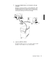
Страница 101: ...h machine that has the Keylock feature You will find these keys in the envelope in which you found this manual Use the key that permits you to turn the lock to the right 3 Locate the verification disk...

Страница 102: ...cking lever of diskette drive 4000 to the vertical position i JCLock n L n Vecbcal Po t on b Insert the verification diskette in the diskette drive slot as shown Push the diskette all the way to the b...

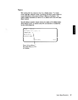
Страница 103: ...Locate keyboard 0 and observe this display It may take a few seconds for this display to appear THIS IS YOUR 5280 VERIFICATION PROGRAM Press ENTER to continue j l ___________J User s Setup Procedures...

Страница 104: ...presentative A2 If the machines buzz when you set the Power switches to 1 On position check for the following The brightness and contrast control may have to be adjusted The verification diskette is i...

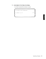
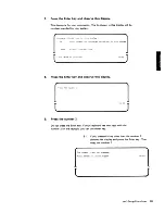
Страница 105: ...continue O 02 8 Press the Enter key and observe this display l ____5 01 9 Press the number 2 Do not press the Enter key If your keyboard has two keys with the number 2 on the keytops you can use eith...

Страница 106: ...ess the Enter key Then rekey the letter Z The letter Z was not pressed Press ENTER to reshow proMPt 51 04 l ___ 12 Observe this display Do Not press the Enter key at this time This is the program load...

Страница 107: ...0 0 2 0 3 0 Repeat step 9 through step 12 for each keyboard maximum of four keyboards on your system When you have completed steps 9 through 13 for each keyboard on your system read the progress check...

Страница 108: ...ram name c Press the Field or Field Exit key d Key 4000 after the words Device address e Press the Enter key 15 If this display appears key the number 1 and press the Enter key This display will appea...

Страница 109: ...on keyboard and observe display If these do not correspond refer to manual ABCDEFGHIJKLMNOPQRSTUVWXYZ0123456789 ENTER to terminate 01 52 03 J If some of the keys that you pressed do not i8Y the chara...

Страница 110: ...f you have completed step 15 through step 21 for each keyboard go to the progress check block and continue to the next step 22 Move to the next higher numbered keyboard and do the following a Ensure t...

Страница 111: ...Device address e Press the Enter key 24 Observe this display What type of drive do you want to test Options are 1 1 Single density 2 2D Double density _ Press ENTER 53 01 J 25 Determine the type of d...

Страница 112: ...e address F l ess ENTER 53 02 J 29 Determine the device address of the diskette drive where the verification diskette is located The device address is the four digit number on the label next to the di...

Страница 113: ...eset key The following display will appear Test terminated 2 Ex i t op t ion Press ENTER 53 79 E2 Press the number 1 then press the Enter key Repeat step 24 through step 31 If the top line of the disp...

Страница 114: ...Observe this display a Press the number 1 if you have more diskette drives to check out b Press the number 2 if this is the last diskette drive to check out c Press the Enter key Test COfllP Lete Op t...

Страница 115: ...______F_ r_es_s __ E_NT_E_R____________________ 53_ _0_2 Jr 38 Determine the device address of the diskette drive where the verification diskette is located The device address is the four digit number...

Страница 116: ...tarts blinking press the Reset or Error Reset key The following display will appear Test terminated Options are 1 Restart 2 Ex i t option _ Press ENTER 3 79 F2 Press the number 1 then press the Enter...

Страница 117: ...the Reset or Error Reset key The following display will appear Options ar i Res tal t 2 Exit opt ion PrOps ENTER G2 Press the number 1 then press the Enter key Repeat step 24 through step 42 If the t...

Страница 118: ...stem 46 Observe this display Press the number 1 if you have more diskette drives to check out Press the number 2 if this is the last diskette drive to check out Press the Enter key Test COftlp tete Op...

Страница 119: ...gress check block and continue to the next step PROGRESS CHECK 1 You should have keyed a 2 and a Z at each keyboard on your system 2 You should have keyed the characters ABC XYZ and 012 789 at each ke...

Страница 120: ...TPRNT after the words Program name c Press the Field or Field Exit key d Key 4000 after the words Device address e Press the Enter key 52 Observe this display and do the following a Key the printer ma...

Страница 121: ...ve this display Press the Enter key For this system checkout procedure use the automatically selected option of 2 Do you want continuous operation lp t i cmS aloe i Yes 2 No 54 02 User s Setup Procedu...

Страница 122: ...display starts blinking press the Reset or Error Reset key The following display will appear Op t ion H e Ex i t Sel ect op i n t J H2 Press the number 1 then press the Enter key Repeat step 52 throu...

Страница 123: ...step Test COltlPlete Opt iORS He L Rest ll t 2 Ex i t Select opt ion _ F l SS ENTEr 4 7B l J PROGRESS CHECK 1 You should have keyed a 2 and a Z at each keyboard on your system 2 You should have keyed...

Страница 124: ...WXYZ 0123456189 0123456189 0123456789 0123456189 0123456189 0123456189 0123456789 0123456789 abcdef9hijklMnop rstuvWXYl abcdefghijklMnop rstuvwxyZ abcdefghijkLMnoP rstuvwxyZ abcdefghijklMnOpqrstuvwxyZ...

Страница 125: ...the left 58 Move to keyboard 0 and do the following a Ensure that the verification diskette in diskette drive 4000 b Key TeOM after the words Program name c Press the Field or Field Exit key d Key 40...

Страница 126: ...re type go to step 70 If you pressed the number 3 for the integrated modem feature type go to step 74 62 Observe this display then press the Enter key For this system checkout procedure use the automa...

Страница 127: ...eset or Error Reset key The following display will appear Test Terffiinated Opt ions ll e i I ESTART 2 EXIT Select option 2 Press ENTER 57 79 t J 12 Press the number 1 then press the Enter key Repeat...

Страница 128: ...cally selected option of 2 Does the COMMunications Cable have a TEST OPERATE switch See Manual Options are i YES 2 NO op t ion 2 Pl es5 EtHER 57 03 J 65 Press the Enter key 66 Observe this display Do...

Страница 129: ...ctor is on the end of the communications cable Wrap Connector b If the end of the cable has a Test Operate switch set it to the operate position c Press the Enter key Test Operate Switch Operate Posit...

Страница 130: ...ts blinking press the Reset or Error Reset key The following display will appear Test Ter ill i nated 1 F ESH RT 2 EXIT SeL ict option Pr ess EN1EF l ___ J2 Press the number 1 then press the Enter key...

Страница 131: ...77 l Test C OfllP I FJte Opticlns al 0 1 I est a ro t Ex i t Sel ect Dption 70 Observe this display Do not press the Enter key Prepare the Wrap Connector see Manual ENTER to continue 71 Do the follow...

Страница 132: ...blinking press the Reset or Error Reset key The following display will appear Test Terminated j F E STf Fn EXIT Sf l pct option r Prpss FNTEF l J K2 Press the number 1 then press the Enter key Repeat...

Страница 133: ...or approximately 20 seconds Communications test in process t 57 02 J L1 If the top line of the display starts blinking press the Reset or Error Reset key The following display will appear Tesot TE rOl...

Страница 134: ...___ 77 Read the progress check block and go to the next step PROGRESS CHECK 1 You should have keyed a 2 and a Z at each keyboard on your system 2 You should have keyed the characters ABC XYZ and 012 7...

Страница 135: ...ached and do the following a Key TKBD after the words Program name b Press the Field or Field Exit key c Key 4000 after the words Device address d Press the Enter key 81 Observe this display WorKstati...

Страница 136: ...his manual Magnetic Stripe Reader Test Card Magnetic Stripe b Position the magnetic stripe reader so that the wide end of the slot is to your right Magnetic Stripe Reader c Place the test card so that...

Страница 137: ...g for the display in step 84 If the display in step 84 does not appear call your service representative Magnetic stripe reader tested Stripe reader error badge or press ENTER to terminate J M2 If the...

Страница 138: ...leted o D o D You can have a maximum of four magnetic stripe readers on your system 89 Move to the next higher numbered keyboard data station that has a magnetic stripe reader attached and do the foll...

Страница 139: ...moved the blank diskette 2D into and out of every diskette 2D drive on your system 4 If your system has a printer s you should have observed each printer print a test pattern 5 If your system has a co...

Страница 140: ...em in the holders provided in the IBM binder containing the IBM 5280 Machine Verification Manual Place the magnetic stripe reader test card if used in the same holder with the verification diskette If...

Страница 141: ...tends from the back of the controller 5288 or 5285 as follows a Determine the communications type first by looking at the end of the communications cable and second by looking at the following illustr...

Страница 142: ...ctor 15 pin Modem or Service Channel Unit Connector If you have the above communications type go to step 3 Local DDSA Communications Line _ Connector 15 pin 15 pin Wrap Connector If you have the above...

Страница 143: ...Assembly Wrap ordered from IBM Connector L ___________________________ _ If you have the above communications type go to step 5 1200 BPS Integrated Switched Communications Line Connected to a 5288 or...

Страница 144: ...nnected to a 5288 or 5285 Phon Jack Connector COT Coupler wall mounted If you have the above communications type go to step 7 CBS Coupler wall mounted 3 You have the EIA or DDSA communications line Do...

Страница 145: ...channel service unit and turn the thumbscrews until tight From 5288 or 5285 Modem or Channel Service Unit It is probably located on a table near the display station d Push the connector into the tele...

Страница 146: ...setup 4 You have the local DDSA communications line Do the following a Remove the wrap connector by pulling straight out b Put the wrap connector in the protective recess area of the machine verificat...

Страница 147: ...machine verification binder c Push the connector into the telephone line socket TelePhone Line Socket it is probably located 0C on or near a wall C Connector Noto The telephone line socket should hav...

Страница 148: ...lephone White Black Wire To DT Thumbscrews Ii OR Coupler Terminal SH SG DA CCT OH RI DT DR Connector Wire Color Red Gray Yellow Brown Blue Violet White Black Receiving Connector Note The data coupler...

Страница 149: ...connector by pulling straight out Wrap Connector b Put the wrap connector in the protective recess area of the machine verification binder c Push the connector into the telephone line socket From a 5...

Страница 150: ...e Socket Connector Connector COT Type Data Coupler It is probably located on a wall or by a telephone Wh ite Red Wire DT CBS Type Data Coupler Coupler Wire Terminal Color SH Red SG Gray DA Yellow CCT...

Страница 151: ...lever open 4 If you have the Keylock feature position the key to the locke d position and remove the keys 5 On the 5282 and the 5286 remove the mirrors from each side of the data station and carefull...

Страница 152: ...etainers in while pulling on the cable connector Note Make sure that each keyboard is properly labeled or relabeled with the correct keyboard number b To disconnect the printer cable turn the retainin...

Страница 153: ...Error IBM may use and distribute any of the information you supply in any way it believes appropriate without incurring any obligation whatever You may of course continue to use the information you su...

Страница 154: ...t Department 997 11400 Burnet Road Austin Texas 78758 Please do not staple International Business Machines Corporation General Systems Division 4111 Northside Parkway N W P O Box 2150 Atlanta Georgia...

Страница 155: ......

Страница 156: ...Systems Division 4111 Northside Parkway N W P O Box 2150 Atlanta Georgia 30301 U S A only General Business Group International 44 South Broadway White Plains New York 10601 U S A International GA21 93...

Отзывы: