IBM 5170 Скачать руководство пользователя страница 34

Содержание 5170

Страница 1: ......

Страница 2: ...IBM Service Exchange Center and providing proof of purchase date If this Product is delivered by mail you agree to insure the Product or assume the risk of loss or damage in transit to prepay shippin...

Страница 3: ...Personal Computer _ Hardware Reference library Installation and Setup...

Страница 4: ...r services in your country Products are not stocked at the address below Requests for copies of this product and for technical information about the system should be made to your Authorized IBM Person...

Страница 5: ...tion If peripherals not offered by IBM are used with the equipment it is suggested to use shielded grounded cables with in line filters if necessary INSTRUCTIONS TO USER This equipment generates and u...

Страница 6: ...rews and ground wires are tightly secured Ensure that card slot covers are in place when no card is installed If peripherals not offered by IBM are used with this equipment it is suggested that you us...

Страница 7: ...This section provides a brief description of how to use this manual Section 2 Cover Removal This section shows you how to remove the system unit s cover Section 3 Internal Option Installation This se...

Страница 8: ...on provides a list of things that should be done before you turn the system s power on Section 7 Power On Self Test This section guides you in performing the Power On Self Test and using the Setup pro...

Страница 9: ...nal Computer AT 128KB Memory IBM Personal Computer AT 512KB Memory IBM Personal Computer AT Fixed Disk Installing the First Fixed Disk Installing a Second Fixed Disk IBM Personal Computer AT Serial Pa...

Страница 10: ...rinter IBM Personal Computer Color Printer Paper r IBM Personal Computer AT Serial Adapter External Option Installation Instructions 5 3 IBM Monochrome Display 5 5 IBM Color Display 5 9 IBM Personal C...

Страница 11: ...1 3 SECTION 1 START Contents Things you should know Installing Internal Options 1 4 Installing External Options 1 6 Start 1 1...

Страница 12: ...Notes 1 2 Start...

Страница 13: ...f your system unit If your dealer has setup your system go to CHART 1 Cabling Your System If you are setting up your system and you have not completed the steps on CHART 2 Installing Your Internal Opt...

Страница 14: ...ions that came in the carton with the options listed below IBM Personal Computer AT 256KB Memory Module Kit IBM Personal Computer AT Math Coprocessor IBM Color Graphics Monitor Adapter IBM Monochrome...

Страница 15: ...dapter IBM Binary Synchronous Communications Adapter IBM Personal Computer AT Prototype Adapter IBM Game Control Adapter IBM Personal Computer AT Floor Standing Option IMPORTANT To install an option n...

Страница 16: ...sonal Computer Display Stand IBM Personal Computer Graphics Printer IBM Personal Computer Graphics Printer Stand IBM Personal Computer Color Printer IBM Personal Computer Color Printer Paper Rack IBM...

Страница 17: ...SECTION 2 COVER REMOVAL Contents Cover Removal 2 3 Cover Removal 2 1...

Страница 18: ...Notes 2 2 Cover Removal...

Страница 19: ...ructions in this manual Installation instructions for internal options are located in Section 3 Installation instructions for external options are located in Section 5 Required Tools Medium size flat...

Страница 20: ...ower off 2 Turn all externally attached devices power off printer display etc Be sure that the Key Lock is unlocked turn the key counterclockwise and remove the key 3 Unlocked Position Locked Position...

Страница 21: ...outlet 5 Disconnect all cables from the back of your system unit and note their location 110 J i j Remove the back panel from the rear of your system unit Note The back panel is attached to the syste...

Страница 22: ...ve cover mounting screws Cover Mounting Screws Cover Mounting Screws 8 Remove the cover 7 lC J 11111111111111111111111111111111111111111111 J 9 Continue with Section 3 Internal Option Installation 2 6...

Страница 23: ...Computer AT Serial Parallel Module Kit 3 7 IBM Personal Computer AT Math Coprocessor 3 17 IBM Color Graphics Monitor Adapter 3 21 IBM Monochrome Display and Printer Adapter 3 29 Expansion Option 3 37...

Страница 24: ...ications Adapter 3 105 IBM Binary Synchronous Communications BSC Adapter 3 109 IBM Personal Computer AT Prototype Adapter 3 115 IBM Game Control Adapter 3 121 IBM Personal Computer AT Floor Standing O...

Страница 25: ...tive Devices Some of your options can be damaged by static discharge To prevent this damage the options are wrapped in anti static bags Certain precautions must be taken before removing an option from...

Страница 26: ...i static bag Hold option adapters by the edges only Avoid touching the components or connections Hold diskette drives and fixed disk drives by their metal frames Hold modules by the ends Avoid touchin...

Страница 27: ...is the suggested order for installation Refer to the table of contents for this section to find the starting page number for your option installation instructions If your system unit s cover has not b...

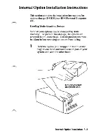
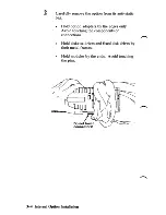
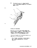
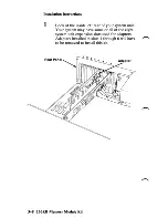
Страница 28: ...Notes 3 6 Internal Option Installation...

Страница 29: ...IBM Personal Computer AT 256KB Memory Module Kit If your system has not been installed go to CHART 2 Installing Your Internal Options before installing this option 256KB Memory Module Kit 3 7...

Страница 30: ...e left rear of your system unit Your system may have some or all of the eight system unit expansion slots used for adapters Adapters installed in slots 1 through 6 will have to be removed to install t...

Страница 31: ...2 Remove the screws that hold the adapters in place Save the screws for the installation of the adapters 256KB Memory Module Kit 3 9...

Страница 32: ...the adapter by the top and lift Make a note of the slot from which you remove each adapter Warning Put your adapters in a safe place They can be damaged if not handled r carefully 3 10 lS6KB Memory Mo...

Страница 33: ...4 Repeat Steps 2 and 3 until the adapters in expansion slots 1 through 6 are removed 256KB Memory Module Kit 3 11...

Страница 34: ...5 Familiarize yourself with the figure below Top View of System Board Keyboard Connector System Unit Expansion Slots r _____ __________ A Front 3 12 256KB Memory Module Kit...

Страница 35: ...d with the connector before the module is pressed in place Improperly inserted modules can cause damage to the module or the system board Module Module Pins l l Notch Connector 7 Check each module to...

Страница 36: ...ters you removed in Steps 2 and 3 Check the notes you made in Step 3 and install the adapters in their proper slots Hold each adapter by the top and press it firmly into its expansion slot 3 14 2S6KB...

Страница 37: ...nstalled 10 Locate the Setup Information fold out at the back of this manual and circle the Base Memory size With all four rows of memory modules installed the Base Memory size 512K bytes 11 If you ha...

Страница 38: ...Notes 3 16 2S6KB Memory Module Kit...

Страница 39: ...IBM Personal Computer AT Math Coprocessor If your system has not been instaUed go to CHART 2 Installing Your Internal Options before instaUing this option Coprocessor 3 17...

Страница 40: ...Installation Instructions 1 Assemble the safety protector as shown below Inserting slot A into slot B Inserting slot C into slot D 3 18 Coprocessor...

Страница 41: ...ns of the safety protector should be on the top of the coprocessor Warning The coprocessor is static sensitive Reduce static by touching the system frame with one hand while installing the coprocessor...

Страница 42: ...ssor firmly into place Make sure the notch on the coprocessor lines up with the notch on its connector Top View of System Board Front 4 If you have any other internal options that need to be installed...

Страница 43: ...IBM Color Graphics Monitor Adapter If your system has not been installed go to CHART 2 Installing Your Internal Options before installing this option Color Graphics Monitor Adapter 3 21...

Страница 44: ...ion slot 1 or 7 Note The Color Graphics Monitor Adapter should be installed in expansion slot 1 If expansion slot 1 is already being used install this adapter in expansion slot 7 These numbers are 1 2...

Страница 45: ...lds the expansion slot s cover in place Save the screw for the installation of the adapter Note Expansion slot 1 does not come with an expansion slot cover Rear Panel Expansion Slot s Cover Color Grap...

Страница 46: ...Look at the IBM Personal Computer AT Fixed Disk and Diskette Drive Adapter installed in expansion slot 8 as a reference Note Your IBM Personal Computer AT comes with support brackets installed for all...

Страница 47: ...4 Install the screw you removed in step 2 Color Graphics Monitor Adapter 3 25...

Страница 48: ...switch for the primary display the display that you want to come on when you turn your system unit s power on For color as the primary display push the switch toward the front of your system unit For...

Страница 49: ...etup program on your Diagnostics diskette after all your options are installed If you have any other internal options that need to be installed install them now If not go to Section 4 Cover Installati...

Страница 50: ...Notes 3 28 Color Graphics Monitor Adapter...

Страница 51: ...BM Monochrome Display and Printer Adapter If your system has not been installed go to CHART 2 Installing Your Internal Options before installing this option Monochrome Display and Printer Adapter 3 29...

Страница 52: ...er should be installed in expansion slot 1 If expansion slot 1 is being used this adapter can then be installed in any available expansion slot These numbers are 1 2 3 4 5 6 7 8 located on the back of...

Страница 53: ...sion slot s cover in place Save the screw for the installation of the adapter Note Expansion slot 1 does not come with an expansion slot cover save this screw t Rear Panel Expansion Slot s Cover Monoc...

Страница 54: ...k at the IBM Personal Computer AT Fixed Disk and Diskette Drive Adapter installed in expansion slot 8 as a reference Note Your IBM Personal Computer AT comes with support brackets installed for all ex...

Страница 55: ...4 Install the screw you removed in step 2 Monochrome Display and Printer Adapter 3 33...

Страница 56: ...t No Set the display switch for the primary display the display that you want to come on when you turn your system unit s power on For color as the primary display push the switch toward the front of...

Страница 57: ...program on your Diagnostics diskette after all your options are installed If you have any other internal options that need to be installed install them now If not go to Section 4 Cover Installation M...

Страница 58: ...Notes 3 36 Monochrome Display and Printer Adapter...

Страница 59: ...AT 128KB Memory Expansion Option a aa a rnaaa arn rn rn rnl1mrnrnrnrn urn rn OO If your system has not been installed go to CHART 2 Installing Your Internal Options before installing this option 128KB...

Страница 60: ...is option Only one IBM Personal Computer AT I28KB Memory Expansion Option can be installed in your machine 1 The IBM Personal Computer AT I28KB Memory Expansion Option may be installed in expansion sl...

Страница 61: ...2 Remove the screw that holds the expansion slot s cover in place Save the screw for the installation of the adapter Save this screw t Rear Panel Expansion Slot s Cover 128KB Memory Expansion 3 39...

Страница 62: ...y the top and firmly press it into the expansion slot making certain the adapter is in the support bracket Use the adapter installed in expansion slot 8 as a reference Adapter Support Brackets 3 40 12...

Страница 63: ...are installed 5 Locate the Setup Information fold out at the back of this manual and circle the Base Memory size With the 128KB Memory Expansion Option installed Base Memory size 640K bytes 6 If you h...

Страница 64: ...Notes 3 42 128KB Memory Expansion...

Страница 65: ...IBM Personal Computer AT 5I2KB Memory Expansion Option If your system has not been installed go to CHART 2 Installing Your Internal Options before installing this option S12KB Memory Expansion 3 43...

Страница 66: ...imum memory capacity of 512K bytes before you install this option The IBM Personal Computer AT 512KB Memory Expansion Option may be installed in expansion slots 2 through 6 These numbers are 1 2 3 4 5...

Страница 67: ...2 Remove the screw that holds the expansion slot s cover in place Save the screw for the installation of the adapter Save this screw t Rear Panel Expansion Slot s Cover 512KB Memory Expansion 3 45...

Страница 68: ...3 Use a ball point pen to set the memory switches The chart on the next page shows you how to set the memory switches 3 46 512KB Memory Expansion...

Страница 69: ...mory Expansion Adapter 4th 512KB Memory Expansion Adapter 5th 512KB Memory Expansion Adapter number of 512KB Memory Expansion adapters installed Use the information on this chart and set the memory sw...

Страница 70: ...this manual and circle the Total Expansion Memory size One 512KB Memory Expansion option installed 512K bytes Two 512KB Memory Expansion options installed 1024K bytes Three 512KB Memory Expansion opti...

Страница 71: ...the top and firmly press it 6 into the expansion slot making certain the adapter is in the support bracket Use the adapter installed in expansion slot 8 as a reference Adapter Support Brackets S12KB M...

Страница 72: ...7 Install the screw you removed in step 2 8 If you have any other internal options that need to be installed install them now If not go to Section 4 Cover Installation 3 50 512KB Memory Expansion...

Страница 73: ...er AT High Capacity Diskette Drive IBM Personal Computer AT Double Sided Diskette Drive High Capacity Diskette Drive Double Sided Diskette Drive If your system has not been installed go to CHART 2 Ins...

Страница 74: ...Installation Instructions 1 Remove the two screws holding the cover plate and remove the cover plate Cover Plate Screws Front View 3 52 Diskette Drive...

Страница 75: ...w 4 Mounting Screws and 3 Clips Remove the mounting screw and two mounting clips from the position shown below Replace one of the clips and the mounting screw Note The remaining clip will be used late...

Страница 76: ...Slide diskette drive A out approximately 50 75 4 mm 2 3 in but do not disconnect the cables Diskette Drive A G1L 50 75 mm 2 3 in Side View 3 54 Diskette Drive...

Страница 77: ...drive you are installing It is no longer needed Note To remove the terminating resistor insert a small flat blade screwdriver under the resistor and lift up Not on all drives Terminating Resistor D D...

Страница 78: ...Slide drive B into the center slot of your system 6 unit until it is even with drive A I Diskette Drive A DlskaHe D ve B I Center Slot II L Side View 3 56 Diskette Drive...

Страница 79: ...7 Find the connector labeled B located behind the diskette drives I __ L 1 11_ _ iiA Fixed Disk Drive C b Diskette Drive B Locating Key Diskette DriveA Diskette Drive 3 57...

Страница 80: ...B and press the connector firmly into place Look at the connector on drive A for reference Note Depending on the number of drives you have installed in your system you may have extra cable connectors...

Страница 81: ...9 Find the connector labeled p12 front VieW Diskette Dri e 3 59...

Страница 82: ...10 Connect the P12 Look at the conn tnordt diskette drive B fIve A f or reference Con nector P1 2 Diskette Drive B Side View 3 60 Diskette D rive...

Страница 83: ...re to diskette drive B Look at the ground wire on drive A for reference Note You may have only one free ground wire Ground wire located here Front View C O d Diskette Drive B P X J Ground Wire Side Vi...

Страница 84: ...12 Slide diskette drives A and B into your system unit and install the four clips and mounting screws Mounting Screws and Clips Front View 3 62 Diskette Drive...

Страница 85: ...13 Push the cables down and out of the way They should be no higher than the power supply Cables Power Supply o Side View Diskette Drive 3 63...

Страница 86: ...emoved in Step 1 Remove the two screws and faceplate They are no longer needed Diskette Face Plate 0 0 0 0 000 J 0 0 0 Cover Plate Screws 15 Install the cover plate and two screwS c Cd r 1 r d C 1 v c...

Страница 87: ...16 Rotate the diskette drive lever open counterclockwise l Front View 17 Remove the shipping insert Front View Diskette Drive 3 65...

Страница 88: ...his manual and circle the drive type for diskette drive B The High Capacity Diskette drive has no special markings The Double Sided Diskette drive is identified by a large asterisk below the in use li...

Страница 89: ...IBM Personal Computer AT Fixed Disk Drive If your system has not been installed go to CHART 2 Installing Your Internal Options before installing this option Fixed Disk 3 67...

Страница 90: ...k drive and void the warranty These instructions are used to install either your first or r second fixed disk drive If this is your first fixed disk drive go to the next page to begin If this is your...

Страница 91: ...InstaUing the First Fixed Disk Drive 1 Remove the tWO screws and clips rrl1 III Mounting Screws and Clips Front View Fixed Disk 3 69...

Страница 92: ...2 Disconnect the power supply connector from the load resistor Remove the two screws and load resistor They are no longer needed Power Supply Connector r Load Resistor Rear View 3 70 Fixed Disk...

Страница 93: ...3 Slide the lilted disk drive into the slot until its Iront panel is approximately 50 15 rom 2 3 in from your system unit s frame front VieW Fixed Disk 3 71...

Страница 94: ...rs on the fixed disk drive signal cable They connect to the fixed disk drive s printed circuit board in only one way The signal cable comes installed in your system unit Fixed Disk Drive C Diskette Dr...

Страница 95: ...with the locating slot on fixed disk drive C and press the connector firmly into place Note Depending on the number of drives you have installed in your system you may have extra cable connectors Fixe...

Страница 96: ...d disk drive data cable It connects to the fixed disk drive s printed circuit board in only one way The data cable comes in the carton with your fixed disk drive 7 Connect the data cable to the fixed...

Страница 97: ...onnect the data cable to the Fixed Disk and Diskette drive adapter as shown Notice that pin 4 is blank and aligns with the plugged hole 4 in the data cable connector Data Cable Connector Fixed Disk 3...

Страница 98: ......

Страница 99: ...10 Slide the fixed disk drive into your system unit Connect the PI0 connector to the fixed disk drive Power connector Back View Fixed Disk 3 77...

Страница 100: ...11 Connect the ground wire to the fixed disk drive Note You may have only one free ground wire Ground Wire Back View 3 78 Fixed Disk...

Страница 101: ...12 Install the ountinll cliPS and screWs N ounting screWs and CUps sacK ieW FiJled Disk 3 79...

Страница 102: ...stalled 13 Locate the Setup Information fold out at the back of this manual and record the fixed disk drive type number by using the following example I Type Number 14 If you have any other internal o...

Страница 103: ...Installing a Second Fixed Disk Drive 1 Remove the two screws holding the cover plate and remove the cover plate Cover Plate Screws Front View Fixed Disk 3 81...

Страница 104: ...2 Remove the two mounting screws and clips from diskette drive A E 3 t l 1 c c d 5 7 9 Mounting Screws and Clips Front View 3 82 Fixed Disk...

Страница 105: ...Slide diskette drive A out approximately 50 75 3 mm 2 3 in but do not disconnect the cables Diskette Drive A GIL 50 75 mm 2 3 in Side View Fixed Disk 3 83...

Страница 106: ...the terminating resistor from the fixed disk drive It is no longer needed Note To remove the terminating resistor insert a small flat blade screwdriver under the resistor and lift up Terminating Resi...

Страница 107: ...sk drive data cable It connects to the fixed disk drive s printed circuit board in only one way The data cable comes in the carton with your fixed disk drive Connect the data cable to the fixed disk d...

Страница 108: ...ive UPright Guide the data 7 cable as you slide the drive into the bottom slot of your system unit until its front panel is even with drive A Diskette Drive A Fixed Disk Drive D L 50 75 mm 2 3 in Side...

Страница 109: ...t the data cable to the Fixed Disk and Diskette Drive adapter as shown Notice that pin 4 is blank and aligns with the plugged hole 4 in the data cable connector Data Cable Connector Front View Fixed D...

Страница 110: ...isk drive signal cable They connect to the fixed disk drive s printed circuit board in only one way The signal cable comes installed in your system unit Fixed Disk Drive C Locating Key Diskette Drive...

Страница 111: ...r D with the locating slot on fixed disk drive D and press the connector firmly into place Note Depending on the number of drives you have installed in your system you may have extra cable connectors...

Страница 112: ...11 find the connector labeled pH connector p12 oc o 0000 o OOOOOo FrontVieVi 3 90 Fixed Disk...

Страница 113: ...12 Slide the fixed disk drive into your system Connect the P12 connector to the fixed disk drive Look at the connectors on fixed disk drive C for reference Connector P12 Back View Fixed Disk 3 91...

Страница 114: ...13 Connect the ground wire to the fixed disk drive D Look at the ground wire on fixed disk drive C for reference Ground Wire Back View 3 92 Fixed Disk...

Страница 115: ...14 Push the cables down and out of the way They should be no higher than the power supply Cables Power Supply Side View Fixed Disk 3 93...

Страница 116: ...tup program on your Diagnostics diskette after all your options are installed 15 Locate the Setup Information fold out at the back of this manual and record the fixed disk drive type number by using t...

Страница 117: ...16 Be sure that the fixed disk drive is completely into your system unit and install the cover plate and two screws Cover Plate Screws Front View Fixed Disk 3 95...

Страница 118: ...ystem unit and install the two clips and mounting screws Mounting Screws and Clips Front View 18 If you have any other internal options that need to be installed install them now If not go to Section...

Страница 119: ...IBM Personal Computer AT Serial Parallel Adapter If your system has not been installed go to CHART 2 Installing Your Internal Options before installing this option Serial Parallel Adapter 3 97...

Страница 120: ...olds the expansion slot s cover in place Save the screw for the installation of the adapter Note The IBM Serial Parallel Adapter can be installed in any available expansion slot t Save this screw I t...

Страница 121: ...pter 1 If you are using it as serial adapter 1 no action is required go to the next page If you are using this adapter as serial adapter 2 remove the module 11 and install it as shown below Note To re...

Страница 122: ...apter 1 If you are using it as parallel adapter 1 no action is required go to the next page If you are using this adapter as parallel adapter 2 remove the module 12 and install it as shown below Note...

Страница 123: ...4 Hold the adapter by the top and firmly press it into the expansion slot Serial Parallel Adapter 3 101...

Страница 124: ...3 102 Serial Parallel Adapter 5 Install the screw you removed in step 1...

Страница 125: ...sed in your system unit the IBM Monochrome Display and Printer Adapter is always used by your system unit as parallel adapter 1 LPTl The following combinations show how each parallel adapter is identi...

Страница 126: ...pter X Monochrome Display and Printer adapter with two Serial Parallel adapters Adapters Installed lPTl lPT2 lPT3 IBM Monochrome Display and Printer Adapter X 1st Serial Parallel Adapter X 2nd Serial...

Страница 127: ...ronous Data Link Control SDLC Communications Adapter If your system has not been installed go to CHART 2 Installing Your Internal Options before installing this option Synchronous Data Link Control SD...

Страница 128: ...lot s cover in place Save the screw for the installation of the adapter Note The Synchronous Data Link Control SDLC Communications Adapter can be installed in any available expansion slot __ Save this...

Страница 129: ...2 Hold the adapter by the top and firmly press it into the expansion slot Synchronous Data Link Control SDLC 3 107...

Страница 130: ...stall the screw you removed in step 1 4 If you have any other internal options that need to be installed install them now If not go to Section 4 Cover Installation 3 108 Synchronous Data Link Control...

Страница 131: ...ary Synchronous Communications BSC Adapter o If your system has not been installed go to CHART 2 Installing Your Internal Options before installing this option Binary Synchronous Communications Adapte...

Страница 132: ...ot s cover in place Save the screw for the installation of the adapter Note The Binary Synchronous Communications Adapter can be installed in any available expansion slot f Save this screw t Rea Panel...

Страница 133: ...per clip on pins 2 and 4 selects the primary mode Installing the jumper clip on pins 1 and 3 selects the alternate mode Install the jumper clip according to your needs Connectors P 1 and P 2 must have...

Страница 134: ...3 Hold the adapter by the top and firmly press it into the expansion slot 3 112 Binary Synchronous Communications Adapter...

Страница 135: ...4 Install the screw you removed in step 1 Binary Synchronous Communications Adapter 3 113...

Страница 136: ...5 If you have any other internal options that need to be installed install them now If not go to Section 4 Cover Installation 3 114 Binary Synchronous Communications Adapter...

Страница 137: ...IBM Personal Computer AT Prototype Adapter If your system has not been installed go to CHART 2 Installing Your Internal Options before instalUng this option Prototype Adapter 3 115...

Страница 138: ...Instructions 1 The mM Personal Computer AT Prototype Adapter can be installed in expansion slots 2 through 6 These numbers are 1 2 3 4 5 6 7 8 located on the back of this panel Rear Panel 3 116 Proto...

Страница 139: ...2 Remove the screw that holds the expansion slot s cover in place Save the screw for the installation of the adapter Save this screw Rear Panel t Expansion Slot s Cover Prototype Adapter 3 117...

Страница 140: ...retaining bracket to the back non component side of the Prototype Adapter The retaining bracket and mounting screws are included with your adapter Component Side Bracket Mounting Screws _ 3 118 Proto...

Страница 141: ...y the top and firmly press it into the expansion slot making certain the adapter is in the support bracket Use the adapter installed in expansion slot 8 as a reference Support Brackets Front Panel Pro...

Страница 142: ...now If not go to Section 4 Cover Installation Note As sold by the manufacturer this Prototype card does not require certification under the FCC s rules for Class B devices The user is responsible for...

Страница 143: ...IBM Game Control Adapter If your system has not been installed go to CHART 2 Installing Your Internal Options before installing this option Game Control Adapter 3 121...

Страница 144: ...that holds the expansion slot s cover in place Save the screw for the installation of the adapter Note The Game Control Adapter can be installed in any available expansion slot Save this screw t Expan...

Страница 145: ...2 Hold the adapter by the top and firmly press it into the expansion slot Game Control Adapter 3 123...

Страница 146: ...3 Install the screw you removed in step 1 4 If you have any other Internal options that need to be installed install them now If not go to Section 4 Cover Installation 3 124 Game Control Adapter...

Страница 147: ...IBM Personal Computer AT Floor Standing Option If your system has not been installed go to CHART 2 Installing Your Internal Options before installing this option Floor Stand 3 125...

Страница 148: ...chrome Display and Printer Adapter are located in this section Warning To prevent a permanent loss of data on the fixed disk drive we recommend that all files be backed up and that the head be parked...

Страница 149: ...is option your system unit s cover must be removed and all cables disconnected To remove the system unit s cover see Section 2 Cover Removal Slide the new template into place over the installed templa...

Страница 150: ...2 Look inside the system unit s cover and locate the back side of the IBM Personal Computer AT logo Push on the back of the logo and turn it 90 degrees counterclockwise 3 128 Floor Stand...

Страница 151: ...ions manual Before you install the system unit s cover make sure you have Connected the system unit battery See CHART 1 Installing Your Internal Options Battery Cable Connector Recorded the Setup Info...

Страница 152: ...play Switch If you have installed expansion memory options set the expansion memory option switches See the IBM Personal Computer AT 512KB Memory Expansion Option installation instructions illffi ill...

Страница 153: ...st the rail and slide it onto your system unit o t J 111111111111111111111111111111111111111111111111 Rail Install the five cover mounting screws Note The system unit back panel is not used when you i...

Страница 154: ...e the system unit It weig sap prOXImately fifty pounds 7 Place your system unit d surface and install the PSI e down on the work o guIde rails on the bottom of the system UUIt as shown GUide Rails 1I1...

Страница 155: ...ewdriver into the slots on the bottom of the floor stand front cover gently twist to release the cover Pull the cover bottom out then lift up to remove it from the floor stand Floor Stand Front Cover...

Страница 156: ...Align the guide rails and slots and slide your 9 system unit until it latches into the enclosure Guide Rail Slots 3 134 Floor Stand...

Страница 157: ...10 Set the top of the floor stand front cover on the latch of the floor stand then press the front cover into place Latch 11 Press the Floor Standing Option s back panel into place 0 Floor Stand 3 135...

Страница 158: ...loor Standing Option on the floor and connect the cables to your system unit 13 If you have any external options that need to be installed install them now If not go to Section 6 System Check List 3 1...

Страница 159: ...SECTION 4 COVER INSTALLATION Contents Cover Installation Check List 4 3 Cover Installation 4 1...

Страница 160: ...Notes 4 2 Cover Installation...

Страница 161: ...rations manual IMPORTANT Before you install the system unit cover make sure that you have Connected the system unit battery See CHART 2 Installing Your Internal Options Battery Cable Connector Battery...

Страница 162: ...uctions Display Switch If you have installed expansion memory options set the expansion memory option switches See the IBM Personal Computer AT 512KB Memory Expansion Option installation instructions...

Страница 163: ...r supply Cables Power Supply o Side View 3 Install the system unit s cover Make sure that the cover is under the rail on the frame Lift the cover up against the rail and slide it onto your system unit...

Страница 164: ...Install the five cover mounting screws Cover Mounting Screws Cover Mounting Screws 5 Remove the paper backing from the plastic fasteners on the back panel Rear View of Back Panel 4 6 Cover Installatio...

Страница 165: ...our system unit and press it into place If you have any options to install that attach to the outside of your system unit go to Section 5 External Option InstallationII If not go to Section 6 System C...

Страница 166: ...Notes 4 8 Cover Installation...

Страница 167: ...rsonal Computer Graphics Printer Stand 5 39 IBM Personal Computer Color Printer 5 43 Using Single Sheets of Paper or Forms 5 57 Continuous Paper and Forms Operation 5 58 Forms Thickness Control Lever...

Страница 168: ...Notes 5 2 External Option InstaUation...

Страница 169: ...appear in this section is the suggested order for installation Refer to the table of contents for this section to find the starting page number for your option installation instructions Required Tools...

Страница 170: ...attached devices power off printer display etc 3 Unplug your system unit s power cord from the wall outlet Power Cable 4 Go to the installation instructions that are in this section for the external o...

Страница 171: ...IBM Monochrome Display 7 If your system has not been installed go to CHAR T 2 Installing Your Internal Options before installing this option Monochrome Display S S...

Страница 172: ...in your system If not refer to the option instructions for the display adapter Install the display adapter before continuing DANGER Serious shock hazards exist within the covers of the IBM Monochrome...

Страница 173: ...em Unit 1 Connect the monochrome display s signal cable to the monochrome display adapter and tighten the screws 2 Connect your display s power cable to the back of your system unit D Signal Cable Pow...

Страница 174: ...be installed install them now If not go to Section 6 System Check List Note The operating instructions for your IBM Monochrome Display are located in the Operating your IBM Personal Computer AT secti...

Страница 175: ...IBM Color Display If your system has not been installed go to CHART 2 Installing Your Internal Options before installing this option mM Color Display 5 9...

Страница 176: ...in your system If not refer to the option instructions for the display adapter Install the display adapter before continuing DANGER Serious shock hazards exist within the covers of the IBM Color Disp...

Страница 177: ...1 Cabling Your Display to the System Unit Connect the IBM Color Display signal cable to the color display adapter Signal Cable IBM Color Display 5 11...

Страница 178: ...signed for the user s safety It is to be used with a properly grounded receptacle to avoid possible electrical shock Connect the Power cord to the rear of the IBM Color Display then to a properly grou...

Страница 179: ...to be installed install them now If not go to Section 6 System Check List Note The operating instructions for your IDM Color Display are located in the Operating your IDM Personal Computer AT section...

Страница 180: ...Notes 5 14 IBM Color Display...

Страница 181: ...IBM Personal Computer Display Stand If your system has not been installed go to CHART 2 Installing Your Internal Options before installing this option Display Stand 5 15...

Страница 182: ...nstallation Instructions 1 Place the display stand so the front track faces you Note You may find it easier to position your display on the stand with the display cables disconnected 5 16 Display Stan...

Страница 183: ...2 Lift and gently place the front feet of your display in the track of the display stand f e co o Display Stand 5 17...

Страница 184: ...djust your display by pivoting the stand up or down and by rotating it 4 If you have any other external options that need to be installed install them now If not go to Section 6 System Check List 5 18...

Страница 185: ...IBM Personal Computer Graphics Printer If your system has not been installed go to CHART 2 Installing Your Internal Options before installing this option IBM Graphics Printer 5 19...

Страница 186: ...t refer to the option installation instructions for the printer adapter Install the printer adapter before continuing DANGER Serious shock hazards exist within the covers of the IBM Personal Computer...

Страница 187: ...1 Shipping Screw Removal Raise the printer access cover and lift it from the printer s base as shown IBM Graphics Printer 5 21...

Страница 188: ...2 Using a Phillips screwdriver remove the two shipping screws from the bottom of your printer o o 1 11 1111111111111111 IIII Shipping Screws 5 22 IBM Graphics Printer...

Страница 189: ...nsert one end of the forms rack into the hole in the side of the printer s frame 2 Compress the other side of the rack and insert the end into the hole on that side of the printer s frame IBM Graphics...

Страница 190: ...idge Installation 1 Turn your printer s power off 2 Using your finger move the print head to the center of your printer Print Head 3 Remove the ribbon cartridge from the packing material 5 24 IBM Grap...

Страница 191: ...Grasp the tab in the center of the ribbon cartridge Tab Guide the two tabs on the left side of the ribbon cartridge into the slots on the left side of the printer s frame Tabs Mh IBM Graphics Printer...

Страница 192: ...n cartridge into the two slots on the right side of the printer s frame Press the ribbon cartridge firmly into place 7 Using a pencil or your finger guide the ribbon into the slot between the print he...

Страница 193: ...he knob in the direction of the arrow to remove any slack in the ribbon Carefully move the print head to be sure the ribbon is free to move between the print head and the ribbon shield IBM Graphics Pr...

Страница 194: ...your system unit s power off 2 Connect the printer cable to the appropriate adapter on your system unit 3 Tighten the screws IBM Monochrome Display Serial Parallel or and Printer Adapter Adapter o o o...

Страница 195: ...ke sure that the cable is pressed firmly into the connector and that the spring retainers are snapped into the slots of the connector Remove the grounding screw and place the ground wire on the screw...

Страница 196: ...with a properly grounded receptacle to avoid possible electrical shock Plug the power cable into a properly grounded outlet 6 Note If your printer has a detachable power cord connect it to the printer...

Страница 197: ...rms Installation Make sure your printer s power is off Place the continuous paper or forms behind and below your printer If you have a printer stand that s ideal The floor will also work Printer Stand...

Страница 198: ...3 Center the forms guide roller 4 Open the tractor covers 5 Move the print scale toward the front of your printer Forms Guide Roller Print Scale 5 32 IBM Graphics Printer...

Страница 199: ...ween the forms rack and plastic roller Note Make sure the printer cables are out of the paper path so they do not interfere with the paper Forms Rack Tilt the forms rack up as shown and guide the pape...

Страница 200: ...8 Push the paper into the opening until 76 to 101 mm 3 to 4 in appear in the front 5 34 IBM Graphics Printer...

Страница 201: ...ors by moving the tractor lock levers forward and sliding the tractors to the correct width Tractor r Lock Lever 10 Place the paper s holes over the top of the tractor pins and close the tractor cover...

Страница 202: ...oll the paper up with the roller knob Ensure that the paper is feeding properly Be sure the paper or forms are centered under or behind the printer Do not allow the paper or forms to rub against anyth...

Страница 203: ...ng is too light move the lever toward the rear of the printer if the printing is smeared move the lever toward the front The best position for the lever is as far to the front of the printer as possib...

Страница 204: ...alled install them now If not go to Section 6 System Check List The operating instructions for your IBM Personal Computer Graphics Printer are located in the Operating your IBM Personal Computer AT se...

Страница 205: ...IBM Personal Computer Graphics Printer Stand If your system has not been installed go to CHART 2 Installing Your Internal Options before installing this option Graphics Printer Stand 5 39...

Страница 206: ...pe the surface of the printer stand clean Remove the paper backing from the clip 2 Place the clip on the stand Note The clip cannot be moved once it is in place Align with the edge Align with the edge...

Страница 207: ...the top shelf of the stand 89 mm 3 1 2 in from the rear edge of the stand 4 Connect the printer cable to the connector on your IBM printer and route the cable through the clip Spring Retainers ____ __...

Страница 208: ...forms on the bottom shelf of the stand and insert the paper or forms 6 If you have any other external options that need to be installed install them now If not go to Section 6 System Check List 5 42 G...

Страница 209: ...IBMPersonal Computer Color Printer u your systemhaS not been rostaJled go to CHART 2 Installing Your Internal Options before msta tiDI tbis option IBM Color Printer 5 43...

Страница 210: ...em If not refer to the option instructions for the printer adapter Install the printer adapter before continuing DANGER Serious shock hazards exist within the covers of the IBM Personal Computer Color...

Страница 211: ...wall outlet or to your system unit until you have completed these unpacking instructions You could damage your printer 1 Follow the instructions printed on the shipping carton to remove your printer...

Страница 212: ...of your printer 5 Remove the packing tubes by carefully pulling them up and off the carriage support shaft 6 Remove the print sample Twist Ties Note You may wish to keep the packing tubes and shippin...

Страница 213: ...as set at the factory for the standard U S voltage range You must verify this by looking into the window next to the power cord connector on the back of the printer You will see the number 120 If you...

Страница 214: ...dard 180 236 Vac 200 190 264 Vac 220 9 Compare your required setting with the number visible through the window at the back of your printer This number is the present voltage setting of your printer 1...

Страница 215: ...then remove the fuse from the printer 14 Using a needle nose pliers or similar tool pull the voltage selection card straight out of the printer 15 Arrange the voltage selection card so that the settin...

Страница 216: ...printer and press it all the way in You should now see only the number for your required voltage setting 17 Reinstall the fuse between the clips and close r the window by sliding it to the right Fuse...

Страница 217: ...CablingYour Printer to Your systeDl Turn your system unit s pOwer ofl Note is the intemational symbOl lor on o is the international symbol lor OU 19 Turn your printer s power oll IBM Color Printer 5...

Страница 218: ...pter connector on your system unit The figure below will help you identify it 21 Connect the printer cable to your system unit and tighten the screws in the cable connector 2S Pin Connector Connector...

Страница 219: ...e spring retainers into the slots on the edges of the cable connector 24 Connect the ground wire Remove the nut from the ground stud Remove one of the two star washers Place the ground wire on the stu...

Страница 220: ...power Cord Connection 1 Turn your prin er S power ol 5 54 IBM Color Printer...

Страница 221: ...and plug designed for the user s safety It is to be used with a properly grounded receptacle to avoid possible electrical shock 2 Locate the power cable in the paper feed opening at the back of the p...

Страница 222: ...3 Connect the power cord to the rear of your printer 4 Plug the power cord into a properly grounded wall outlet Caution Connect to a properly grounded receptacle 5 56 IBM Color Printer...

Страница 223: ...loading slots are shown at the end of this section Single sheets can be loaded only at the front loading slot The following two sections describe how to use either type of paper Each section is comple...

Страница 224: ...r forms close to the front loading slot Note The front loading slot is easiest to use when first learning to use the printer If you choose to use the rear or bottom loading slot place a supply of form...

Страница 225: ...3 4 Open the access cover Access Cover Center the print head carriage by sliding it left or right IBM Color Printer 5 59...

Страница 226: ...r toward the front of your printer to the open continuous paper or forms position feed Mode lever 6 Move the Forms Thickness Control lever toward the front of your printer forms Thickness Control leve...

Страница 227: ...7 8 Unlock both tractors by pushing the Tractor Lock levers down Slide both tractors to their outermost positions Left Tractor Right Tractor IBM Color Printer 5 61...

Страница 228: ...9 Lock the left tractor in place by pushing the lock lever up Lett Tractor 5 62 IBM Color Printer...

Страница 229: ...10 Open both tractor doors IBM Color Printer 5 63...

Страница 230: ...ost positions Note This step is for front loading only lett Paper Guide Right Paper Guide 12 Insert continuous paper or forms into the paper loading slot until they just pass the tractors Front loadin...

Страница 231: ...13 Adjust the a erso the holes in the left side align with the left tractor pins IBM Color Printer 5 65...

Страница 232: ...14 Close the left tractor door 15 Adjust the right tractor so the tractor pins align with the holes in the right side of the paper Right Tractor 5 66 IBM Color Printer...

Страница 233: ...ose the tractor door and push the lock lever up 11 the paper buckles unlock the right tractor and slide it to the right Then lock the tractor in place Tractor Door Tractor lock lever IBM Color Printer...

Страница 234: ...1 7 Center the tWO sheet feed rollers betWeen the tractors Sbeet feed Ro ers 5 68 IBM Color Printer...

Страница 235: ...sheet position Note If the printing smears gradually move this lever toward the front of your printer until the smearing stops See Forms Thickness Control Lever on the next page Forms Thickness Contro...

Страница 236: ...inting is too light move the lever toward the rear of the printer if the printing is smeared move the lever toward the front The best position for the lever is as far to the front of the printer as po...

Страница 237: ...aper or forms can also be loaded from the rear or bottom of your printer as shown in the figures below The instructions are the same as for front loading with the exception of Step 11 Rear Loading Li...

Страница 238: ...ms 3 Mode c J Line 4 Feed OR Form Feed Initialize 5 Move the paper to the approximate position you wish to set as the top of form Set your printer to the forms mode Move the paper up or down to the ex...

Страница 239: ...per follow this procedure 1 Turn your printer s power off 2 Open the printer access cover 3 With continuous paper or forms installed unlock both tractors by pushing the Tractor Lock levers down 4 Slid...

Страница 240: ...talled install them now If not go to Section 6 System Check List Note The operating instructions for your IBM Personal Computer Color Printer are located in the Operating your IBM Personal Computer AT...

Страница 241: ...r continuoUS paper or forms turo to ContinUOUS Paper and forms operation Paper Installation 1 Remove any paper presently in your printer 2 Turn your printer s power off 3 open the access cover AccesS...

Страница 242: ...Center the print head carriage by sliding it left or right Print Head 5 Move the Feed Mode lever toward the rear of the printer to the closed single sheet position Feed Mode Lever 5 76 IBM Color Print...

Страница 243: ...6 7 Unlock both tractors by pushing the Tractor Lock levers down Tractor Slide both tractors to their outermost positions Left Tractor Right Tractor IBM Color Printer 5 77...

Страница 244: ...S sUde the left paper guide untll its right edge is aligned with the arrowhead on the scale lett Pa er Guide 9 Slide the right paper guide to the far right Ri bt Paper Guide 5 78 IBM Color Printer...

Страница 245: ...10 Close the access cover 11 Turn your printer s power on I Mode IBM Color Printer 5 79...

Страница 246: ...12 Wait for the Fault light to come on approximately 10 seconds 5 80 IBM Color Printer...

Страница 247: ...he top left edge of a test sheet of paper against the left paper guide do not push the paper up into the feed mechanism 14 Slide the right paper guide against the right edge of the paper IBM Color Pri...

Страница 248: ...ically moves the paper to the first printable line approximately 19 mm 3 4 in below the top edge of the ribbon 16 Press the Ready button once to turn the Ready light Off I 17 Press and hold the Line F...

Страница 249: ...18 Turn your printer s power off 19 Open the accesS cover 20 Open both tractor doors IBM Color Printer 5 83...

Страница 250: ...d rollers on the tractor drive rail so the outside edges of the rollers are even with the edges of the paper EveD Here 22 Slide each tractor against its respective sheet feed roller Sheet Feed Roller...

Страница 251: ...lock the tractors in place by pushing the Tractor Lock levers up Tractor Lock Lever Tractor Door 24 Close the access cover 25 Turn your printer s power on Press the Ready button to turn the Ready lig...

Страница 252: ...aper out of your printer The Fault light will then come on 27 You can now insert a sheet of paper into the front loading slot The paper will automatically advance to the first printable line 7 1 7 I i...

Страница 253: ...inting is too light move the lever toward the rear of the printer if the printing is smeared move the lever toward the front The best position for the lever is as far to the front of the printer as po...

Страница 254: ...3 Mode c J Line 4 Feed OR Form Feed T Initialize 5 Move the paper to the approximate position you wish to set as the top of page Set your printer to the forms mode Move the paper up or down to the ex...

Страница 255: ...es 38 1 mm 1 1 2 in from the left edge of the paper If you want to start your lines farther to the right see ESC X under Printer Control Codes To adjust the paper position 1 Move the front paper guide...

Страница 256: ...installed install them now If not go to Section 6 System Check Note The operating instructions for your IBM Personal Computer Color Printer are located in the Operating your IBM Personal Computer AT s...

Страница 257: ...IBM Personal Computer Color Printer Paper Rack this option u your printer ba not been set up do so before insta liDl IBM Color Printer Paper Rack 5 91...

Страница 258: ...et your Paper Rack into the holes in the top of your printer as shown 2 If you have any other external options that need to be installed install them now If not go to Section 6 System Check List 5 92...

Страница 259: ...IBM Communications Cable If your system has not been installed go to CHART 2 Installing Your Internal Options before instaUing this option Communications Cable 25 pin 5 93...

Страница 260: ...in your system If not refer to the option instructions for the communications adapter and install it before continuing 1 Connect the communications adapter cable silver colored end to the communicati...

Страница 261: ...2 Connect the other end of the cable to the modem or any other RS 232 data communications equipment 25 Pin Connector Communications Cable 25 pin 5 95...

Страница 262: ...3 If you have any other external options that need to be installed install them now If not go to Section 6 System Check List 5 96 Communications Cable 25 pin...

Страница 263: ...IBM Personal Computer AT Serial Adapter Cable If your system has not been installed go to CHART 2 Installing Your Internal Options before installing this option Serial Adapter Cable 5 97...

Страница 264: ...d in your system If not refer to the option instructions for the communications adapter and install it before continuing Installation Instructions 1 Connect the Serial Adapter cable 9 pin end to the c...

Страница 265: ...2 Connect the other end of the cable 25 pin end to the modem or any other RS 232 data communications equipment 25 Pin Connector Serial Adapter Cable 5 99...

Страница 266: ...3 If you have any other external options that need to be installed install them now If not go to Section 6 System Check List 5 100 Serial Adapter Cable...

Страница 267: ...SECTION 6 SYSTEM CHECK LIST Contents System Check List 6 3 SYSTEM CHECK LIST 6 1...

Страница 268: ...Notes 6 2 SYSTEM CHECK LIST...

Страница 269: ...ystem unit be sure The 115V 230V selector switch is set to the proper position See CHART 1 Installing Your Internal Options Screwdriver tr o o The system unit cover is on and all five cover screws ins...

Страница 270: ...fi The back panel is on All external devices are connected 6 4 SYSTEM CHECK LIST...

Страница 271: ...Your system unit s power is off ll 1 IIIII111 11III1 0 System Unit Power Switch All externally attached devices power is off printer display etc SYSTEM CHECK LIST 6 5...

Страница 272: ...1 Connect the keyboard to your system unit t 6 6 SYSTEM CHECK LIST...

Страница 273: ...signed for the user s safety It is to be used with a properly grounded receptacle to avoid possible electrical shock 2 Connect the power cable to the system unit Plug the power cable into the wall out...

Страница 274: ...3 Record the serial numbers for any options that you have installed in Appendix B of your Guide to Operations manual 4 Go to the Power On Self Test 6 8 SYSTEM CHECK LIST...

Страница 275: ...SECTION 7 POWER ON SELF TEST Contents Power On Self Test 7 3 POST 7 1...

Страница 276: ...Notes 7 2 POST...

Страница 277: ...television or composite display it must be U S television system NTSC compatible Your display or TV may also cause you to experience data errors while using your diskette or disk drive You can correc...

Страница 278: ...ways of handling your diskettes Proper handling will reduce the possibility of damaging them ego 0 Don t Bend Proper Grasp by Corner 0 ego 0 Improper No Pencils No Clips No Ballpoints When Not In Use...

Страница 279: ...e located in the back of your Guide to Operations manual Insert the Diagnostics diskette into diskette drive A Push the diskette in until you hear it click into place Diagnostics Diskette Diskette Dri...

Страница 280: ...I I I I I I I I I I I I I I I I I I I I I I I I I I I I I I I I I I I I I I I I I I I I I 4 Rotate the diskette drive lever clockwise I I I I I Diskette Drive Lever I III I I 7 6 POST...

Страница 281: ...status lights blink on and off Event 3 The keyboard status lights blink on and off then two short beeps are heard when POST Is complete_ Event 2 Memory size test appears in upper left corner of screen...

Страница 282: ...ckwise Turn your display power on if it has a Power switch 7 Turn all externally attached devices printer TV etc power on 8 Turn your system unit s power on System Unit Power Switch 9 Adjust your disp...

Страница 283: ...an option Note If you received a 302 System Unit Key Lock is Locked message unlock the lock on the front of the system unit before continuing XXXXX KB OK 161 System Options Not Set Run SETUP RESUME F...

Страница 284: ...OPY DISKETTE 3 PREPARE SYSTEM FOR MOVING 4 SETUP 9 END DIAGNOSTICS SELECT THE ACTION DESIRED 1 DOES YOUR SCREEN MATCH THE SCREEN SHOWN ABOVE YES The Power On Self Test has completed Your IBM Personal...

Страница 285: ...fixed disk drive Then it must verify the diskette drive types and memory size The answers to the questions this program will ask are listed on the Setup Information foldout which is in the back of thi...

Страница 286: ...Notes 7 12 POST...

Отзывы: