


v
No
:
Contact
your
next
level
of
support.
This
ends
the
procedure.
Storage
I/O
card
modes
and
jumpers
For
use
by
authorized
service
providers.
The
2748
and
2778
I/O
card
can
run
in
either
compression
mode
or
enhanced
mode.
v
Compression
Mode:
Compression
mode
should
only
be
used
when
you
want
to
run
Integrated
Hardware
Disk
Compression.
In
compression
mode,
the
write
cache
size
is
4
MB.
v
Enhanced
Mode:
Enhanced
mode
has
an
enhanced
write
cache
size.
In
Enhanced
mode,
the
write
cache
size
for
the
2748
I/O
Card
is
26MB,
and
the
maximum
compressed
write
cache
size
for
the
2778
I/O
Card
is
104MB.
Enhanced
mode
also
provides
support
for
Extended
Adaptive
Cache
(by
attachment
of
a
read
cache
device)
and
Extended
Adaptive
Cache
Simulator.
The
following
pages
are
included
here:
v
v
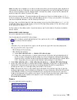
When
an
error
regarding
the
mode
of
the
storage
I/O
card
appears,
the
error
message
indicates
whether
the
jumper
is
missing
or
overridden.
–
If
the
error
message
is
CPPEA20,
the
I/O
card
has
overridden
the
mode
set
by
the
jumper.
See
–
If
the
error
message
is
CPPEA21,
the
I/O
card
has
detected
that
the
jumper
is
missing.
See
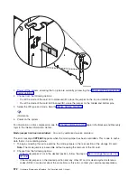
Set
or
change
the
mode
of
an
I/O
card:
For
use
by
authorized
service
providers.
The
2748
and
2778
I/O
card
supports
two
modes:
Compression
and
Enhanced.
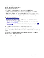
The
rear
of
the
I/O
card
is
marked
with
a
C
,
indicating
compression
mode,
and
an
E
,
indicating
enhanced
mode.
Three
pins
on
the
rear
of
the
I/O
card
determine
the
mode
of
the
card,
depending
on
which
of
the
pins
have
a
jumper
placed
on
them.
The
jumper
may
be
moved
at
any
time,
but
changes
only
take
effect
during
a
system
IPL.
Refer
to
the
illustration
below
while
changing
the
mode
jumper.
Figure
1.
Changing
the
mode
jumper
Analyze
hardware
problems
571
Содержание 270
Страница 2: ......
Страница 12: ...x Hardware Remove and Replace Part Locations and Listings...
Страница 279: ...Figure 3 CCIN 2881 with pluggable DIMM Analyze hardware problems 267...
Страница 281: ...Figure 6 Models 830 SB2 with FC 9074 HSL and SPCN locations Analyze hardware problems 269...
Страница 283: ...Figure 1b Model 840 SB3 processor tower dual line cord Analyze hardware problems 271...
Страница 294: ...01 gif port and LED locations 282 Hardware Remove and Replace Part Locations and Listings...
Страница 295: ...s src rzaq4519 gif locations Analyze hardware problems 283...
Страница 318: ...Figure 2 FC 5088 FC 0588 Expansion I O Unit top view 306 Hardware Remove and Replace Part Locations and Listings...
Страница 415: ...Table 2 Final assembly rear Models 830 and SB2 with FC 9074 continued Analyze hardware problems 403...
Страница 422: ...Table 1 Cover assembly Models 840 and SB3 processor tower 410 Hardware Remove and Replace Part Locations and Listings...
Страница 483: ...Table 1 Cover assembly FC 5095 Expansion I O Tower Analyze hardware problems 471...
Страница 505: ...Table 15 Model 830 SB2 System Unit with FC 9074 Power cables single line cord Analyze hardware problems 493...
Страница 511: ...Table 19 Model 840 SB3 Processor Tower Power cables single line cord Analyze hardware problems 499...
Страница 513: ...Table 21 Model 840 and Model SB3 9079 Base I O Tower Power cables dual line cord Analyze hardware problems 501...
Страница 519: ...Figure 15 Models 870 and 890 Primary I O to CEC interconnection part 1 Analyze hardware problems 507...
Страница 614: ...602 Hardware Remove and Replace Part Locations and Listings...
Страница 618: ...606 Hardware Remove and Replace Part Locations and Listings...
Страница 621: ......
Страница 622: ...Printed in USA SY44 5917 02...