


Power
off
the
system:
Attention:
Powering
off
and
powering
on
a
system
with
multiple
partitions
is
different
than
a
system
with
a
single
partition.
Read
and
understand
the
power
off
and
power
on
procedures
referenced
when
a
procedure
directs
you
to
power
on
or
power
off
a
system
or
partition.
Choose
one
of
the
following:
v
If
the
system
is
operating
under
Dedicated
Service
Tools
(DST),
perform
the
following:
1.
Power
off
the
system
by
selecting
Power
off
the
system
on
the
Start
a
Service
Tool
display.
2.
To
completely
remove
power
from
the
system,
turn
off
the
UEPO
switch,
then
disconnect
both
power
cords
from
the
customer’s
receptacle.
v
If
the
system
is
operating
under
OS/400:
1.
Choose
from
the
following:
–
For
consoles
that
run
iSeries
Access,
a
delayed
power-off
is
required.
Enter
the
PWRDWNSYS
command.
You
must
stop
all
applications,
including
console
applications,
and
subsystems
that
are
running,
before
the
delayed
power-off
operation
is
complete.
–
All
others,
enter
the
PWRDWNSYS
command
to
power
off
the
system.
2.
To
completely
remove
power
from
the
system,
turn
off
the
UEPO
switch,
then
disconnect
both
power
cords
from
the
customer’s
receptacle.
v
If
you
cannot
use
these
methods,
you
can
power
off
the
system
by
using
the
procedure
below.
Control
panel
power
button:
Attention:
Using
the
control
panel
Power
push-button
to
power
off
the
system
may
cause
unpredictable
results
in
the
data
files,
and
the
next
IPL
will
take
longer
to
complete.
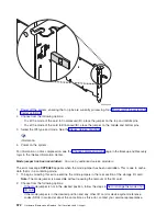
1.
Open
the
control
panel
cover.
2.
Select
Manual
mode
if
it
is
not
already
selected.
See
.
3.
Press
the
Power
button
(white)
on
the
control
panel.
The
Data-Function
display
shows
O?
(the
international
power-off
symbol).
4.
Press
the
Power
button
(white)
on
the
control
panel
again.
Note:
To
cancel
the
power-off
operation,
do
not
press
the
Power
button
a
second
time.
Instead,
press
any
other
control
panel
button.
5.
The
Power
On
light
starts
blinking
at
the
fast
rate
of
one
blink
per
second
as
the
system
powers
off.
The
light
starts
blinking
at
the
slow
rate
of
one
blink
per
three
seconds
when
the
power-off
operation
is
complete.
Does
the
system
power
off
successfully?
v
Yes
:
This
ends
the
procedure.
v
No
:
Perform
the
following:
a.
Press
the
^
or
the
V
button
until
function
08
is
shown
in
the
Function
display.
b.
Press
Enter
.
An
SRC
A100
8008
will
appear
on
the
Data
display.
c.
Press
the
Power
button
(white)
on
the
control
panel.
The
Data-Function
display
shows
O?
(the
international
power-off
symbol).
d.
Press
the
Power
button
(white)
on
the
control
panel
again.
The
system
powers
off
and
the
Power
On
light
blinks
at
the
slow
rate
of
one
blink
per
three
seconds.
Note:
To
cancel
the
power-off
operation,
do
not
select
function
08.
Instead,
press
any
other
control
panel
button.
This
ends
the
procedure.
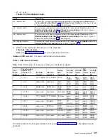
Power
off
a
system
with
multiple
logical
partitions:
Use
the
following
table
to
determine
if
the
system
must
be
powered
off,
or
if
only
the
secondary
partition
that
you
are
servicing
must
be
powered
off.
562
Hardware
(Remove
and
Replace;
Part
Locations
and
Listings)
Содержание 270
Страница 2: ......
Страница 12: ...x Hardware Remove and Replace Part Locations and Listings...
Страница 279: ...Figure 3 CCIN 2881 with pluggable DIMM Analyze hardware problems 267...
Страница 281: ...Figure 6 Models 830 SB2 with FC 9074 HSL and SPCN locations Analyze hardware problems 269...
Страница 283: ...Figure 1b Model 840 SB3 processor tower dual line cord Analyze hardware problems 271...
Страница 294: ...01 gif port and LED locations 282 Hardware Remove and Replace Part Locations and Listings...
Страница 295: ...s src rzaq4519 gif locations Analyze hardware problems 283...
Страница 318: ...Figure 2 FC 5088 FC 0588 Expansion I O Unit top view 306 Hardware Remove and Replace Part Locations and Listings...
Страница 415: ...Table 2 Final assembly rear Models 830 and SB2 with FC 9074 continued Analyze hardware problems 403...
Страница 422: ...Table 1 Cover assembly Models 840 and SB3 processor tower 410 Hardware Remove and Replace Part Locations and Listings...
Страница 483: ...Table 1 Cover assembly FC 5095 Expansion I O Tower Analyze hardware problems 471...
Страница 505: ...Table 15 Model 830 SB2 System Unit with FC 9074 Power cables single line cord Analyze hardware problems 493...
Страница 511: ...Table 19 Model 840 SB3 Processor Tower Power cables single line cord Analyze hardware problems 499...
Страница 513: ...Table 21 Model 840 and Model SB3 9079 Base I O Tower Power cables dual line cord Analyze hardware problems 501...
Страница 519: ...Figure 15 Models 870 and 890 Primary I O to CEC interconnection part 1 Analyze hardware problems 507...
Страница 614: ...602 Hardware Remove and Replace Part Locations and Listings...
Страница 618: ...606 Hardware Remove and Replace Part Locations and Listings...
Страница 621: ......
Страница 622: ...Printed in USA SY44 5917 02...