v
If
the
disk
unit
you
exchanged
is
in
ASP
1,
have
the
customer
see
the
Backup
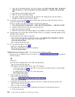
and
Recovery
information.
You
must
restore
the
operating
system
(OS/400
Licensed
Program)
and
all
customer
data.
v
If
the
disk
unit
is
in
a
user
ASP
(ASP
2
through
ASP
16),
data
in
the
ASP
is
lost.
See
the
Backup
and
Recovery
information.
This
ends
the
procedure.
17.
Is
the
failing
unit
missing
from
the
configuration?
v
No
:
Find
another
disk
unit
on
the
system,
other
than
the
load-source
disk
unit.
Continue
with
the
next
step.
v
Yes
:
Go
to
step
26
(See
page
18.
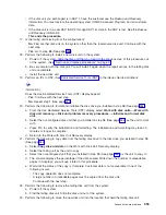
Perform
the
following
to
install
a
new
disk
unit
on
the
system:
a.
Power
off
the
system.
Slide
the
disk
unit
that
you
found
in
the
previous
step
of
this
procedure
out
of
the
system.
(See
b.
Be
very
careful
with
the
disk
unit.
You
will
install
it
again
when
the
repair
actions
to
the
failing
disk
unit
are
complete.
c.
Install
the
new
disk
unit.
19.
Perform
an
IPL
to
DST.
(See
in
the
iSeries
Service
Functions
information.)
Does
the
Use
Dedicated
Service
Tools
(DST)
display
appear?
v
Yes
:
Continue
with
the
next
step.
v
No
:
Repeat
step
1
(See
page
20.
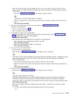
Perform
the
following
to
format
and
initialize
the
disk
drive
you
installed
in
step
18
(See
page
a.
From
the
Use
Dedicated
Service
Tools
(DST)
display,
select
Work
with
disk
units
—>
Work
with
disk
unit
recovery
—>
Disk
unit
problem
recovery
procedures
—>
Initialize
and
format
disk
unit
.
b.
Select
the
nonconfigured
disk
unit
that
you
installed
in
step
18
(See
page
as
the
unit
to
work
with.
c.
Press
F10
to
verify
the
initialization
and
formatting.
The
initialization
and
formatting
may
take
30
minutes
or
longer
to
complete.
d.
Return
to
the
Work
with
Disk
Unit
Recovery
display.
21.
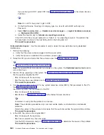
Perform
the
following
to
copy
data
from
the
failing
disk
drive
to
the
disk
drive
you
installed
in
step
18
(See
page
a.
Select
Copy
disk
unit
data
on
the
Work
with
Disk
Unit
Recovery
display.
b.
Select
the
failing
unit
as
the
unit
to
copy.
c.
Select
the
nonconfigured
unit
that
you
installed
in
step
18
(See
page
as
the
unit
to
copy
to.
d.
The
console
displays
the
percentage
of
the
data
copied.
Write
down
the
number
of
unreadable
pages
if
it
displays;
you
will
use
it
later
in
this
procedure.
e.
Wait
until
the
status
of
the
copy
is
Complete
.
Customer
data
is
not
recoverable
if
one
of
the
following
occurs:
v
The
copy
operation
does
not
complete.
v
A
large
number
of
unreadable
pages
must
be
copied
from
the
disk
unit.
Continue
with
the
next
step.
22.
Perform
the
following
to
remove
the
failing
disk
unit
from
the
system:
a.
Power
off
the
system.
b.
Find
the
failing
disk
unit.
Slide
the
disk
unit
out
of
the
system.
23.
Perform
the
following
to
move
the
new
disk
unit
into
the
location
that
held
the
failing
disk
unit:
Analyze
hardware
problems
555
Содержание 270
Страница 2: ......
Страница 12: ...x Hardware Remove and Replace Part Locations and Listings...
Страница 279: ...Figure 3 CCIN 2881 with pluggable DIMM Analyze hardware problems 267...
Страница 281: ...Figure 6 Models 830 SB2 with FC 9074 HSL and SPCN locations Analyze hardware problems 269...
Страница 283: ...Figure 1b Model 840 SB3 processor tower dual line cord Analyze hardware problems 271...
Страница 294: ...01 gif port and LED locations 282 Hardware Remove and Replace Part Locations and Listings...
Страница 295: ...s src rzaq4519 gif locations Analyze hardware problems 283...
Страница 318: ...Figure 2 FC 5088 FC 0588 Expansion I O Unit top view 306 Hardware Remove and Replace Part Locations and Listings...
Страница 415: ...Table 2 Final assembly rear Models 830 and SB2 with FC 9074 continued Analyze hardware problems 403...
Страница 422: ...Table 1 Cover assembly Models 840 and SB3 processor tower 410 Hardware Remove and Replace Part Locations and Listings...
Страница 483: ...Table 1 Cover assembly FC 5095 Expansion I O Tower Analyze hardware problems 471...
Страница 505: ...Table 15 Model 830 SB2 System Unit with FC 9074 Power cables single line cord Analyze hardware problems 493...
Страница 511: ...Table 19 Model 840 SB3 Processor Tower Power cables single line cord Analyze hardware problems 499...
Страница 513: ...Table 21 Model 840 and Model SB3 9079 Base I O Tower Power cables dual line cord Analyze hardware problems 501...
Страница 519: ...Figure 15 Models 870 and 890 Primary I O to CEC interconnection part 1 Analyze hardware problems 507...
Страница 614: ...602 Hardware Remove and Replace Part Locations and Listings...
Страница 618: ...606 Hardware Remove and Replace Part Locations and Listings...
Страница 621: ......
Страница 622: ...Printed in USA SY44 5917 02...


