IBM 1402 Скачать руководство пользователя страница 9

Содержание 1402

Страница 1: ...il g 5 Customer Engineering Reference Manual I v Card Read Punch 8231 002 5...

Страница 2: ...Customer Engineering Reference Manual Card Read Punch...

Страница 3: ...r S31 0150 Pages affected 1 1 3 2 3 19 3 38 3 39 3 41 3 41 2 3 41 3 3 41 5 4 2 7 1 7 2 Date 4 28 67 Specifications contained herein are subject to change from time to time Any such changes will be rep...

Страница 4: ...3 28 3 29 3 30 3 31 3 31 3 32 3 32 3 33 3 33 3 33 3 33 3 33 3 33 3 36 3 36 3 37 3 37 3 38 3 39 3 39 3 40 3 40 3 40 3 41 3 41 Motors Redesigned Punch Feed Card Guides Feed Roll Timing Check Feed Roll...

Страница 5: ...IBM 1402 Card Read Punch...

Страница 6: ...ips e A split shaft held by a set screw is located just above file feed drive shaft Slip both halves of shaft to center inside of castiI g f Put upper magazine in place and slide both halves of shaft...

Страница 7: ...STRUT CLIP SUPPORT ______ PLATE STRUJ CLlP ti SUPPORT PLATE Figure 1 1 File Feed Tray Mounting 1 2 SET SCREW RETAINING SCREW ___ FILE FEED FILLER MOUNTING SCREW NEW STYLE OLD STYLE...

Страница 8: ...LT WEAR TRANS PUSHER SLIDE CAM FOLLOWERS 9 PORT LUBRICATE CARD PUSHER SLIDE SPRING ENDS AND CAMS 17 LUBRICATE STACKER JOGGLER CLUTCH SPRING GREASE FITTING 20 FILTER REPLACE IF DIRT IS VISIBLE FROM INS...

Страница 9: ...REDESIGNED PUNCH FEED IT IS NOT NECESSARY TO REMOVE PUNCH UNIT TO LUBRICATE HOLES HAVE BEEN PROVIDED IN THE SIDE FRAME SO ALL GREASE FITTINGS ARE ACCESSIBLE NOTE 2 BE SURE GREASE COMES OUT AROUND 1ST...

Страница 10: ...ing Procedures near the midpoint of belt width as possible Clutched Feed Roll Drive Belt This procedure is necessary only if the belt is captive REPLACEMENT 1 Remove solar cell unit a Remove plastic c...

Страница 11: ...to center plate assembly and clutch magnet assembly When a complete adjustment is to be made the read clutch locating plate gage 610147 must be used NOTE Use of this gage will ensure a parallel con di...

Страница 12: ...ssembly The clutch pulley includes the dogs and arms REMOYAL 1 If same clutch assembly is to be used spot mark clutch pulley and picker knife cam shaft pulley to belt to retain RLCB s solar CB and pic...

Страница 13: ...utch pulley and operate the arms so that detent and dog fit into high dwell of ratchet 3 Place two thrust bearings against clutch pulley 4 Install clutch retaining clamp and file feed pul ley allowing...

Страница 14: ...ure 10 Check timings a Clutch engagement time 315 1 b Brush impulse CB timing c RCCB timing d RLCB timing File Feed Clutch ADJUSTMENTS 1 With clutch latch against latch step on sleeve loosen split col...

Страница 15: ...Then hopper posts have to be adjusted also Refer to Hopper Adfust ments b On other machines hopper post mounting bar is pinned in position The 003 to 010 clear ance is obtained by shimming between pi...

Страница 16: ...5 Position feed knife arms evenly on shaft so that LATCH Figure 3 8 File Feed Adjustments feed edge of picker knife block travels 020 to 030 beyond trailing edge of card when card is held against hop...

Страница 17: ...be set to b gb d eu on See F gu 8 11 AD JSl ME NTS 1 Set Pring 15 64 017 64 below bolt I card Weight om 0 2 Se end sPringS 7 82 0 15 64 below bo oJ card Welght Card GUides Reier to F gu 3 12 for card...

Страница 18: ...t heel of shortest brush group on scribed line 030 020 NOTE is toward the stacker is toward the hopper b Three group brushes two scribed lines These are used on Model 2 machines and some Model 1 s Set...

Страница 19: ...are 360 apart If not correct brush block on which brushes are furthest from scribed line 3 Dynamically time brushes to wiring diagram by shifting picker knife timing Do not time brushes by shifting th...

Страница 20: ...line up as described in Step 2 FI RST STEPPED FEED ROLL DRI VE BELT DARKENED BELTS ARE UNDER CONTROL OF PUNCH FEED CLUTCH HOTOR PULLEY Figure 3 15 Punch Feed fi g Belts DRIVE MOTOR BELT REPLACEMENT 1...

Страница 21: ...h Unit Drive Belt 11 First Stepped Feed ii Main Drive8elt 1 Roll Drive Belt Punch Clutch Magnet Bracket Assembly iC 2 Time PCCB s a Loosen PCCB adjusting set screws on drive pulley b Set timer index t...

Страница 22: ...pulley clamp ng scr ws TIMING MARKS Figure 3 17 PACB Timing Marks PUNCH UNIT DRIVE BELT REPLACEMENT Do not remove geneva unit when punch unit drive belt is being replaced 1 Loosen idler pulley Instal...

Страница 23: ...r to adjust it Figure 3 21 B 5 With cam follower on high dwell position arma ture backstop plate vertically for 020 to 025 3 14 overlap of armature and latch position horizon tally for 010 to 015 rela...

Страница 24: ...acklash in DYNAMIC TIMER DRIVER Figure 3 19 Punch Timing Belt Tensions PA CAMS 1ST FEED ROLL 8 32 gears If there is too much backlash punching registration will be off If there is no backlash the gear...

Страница 25: ...rance between hop per posts and stack of cards b Adjust clearance by loosening screws in both ends of hopper post mounting bar then shift bar to desired amount 5 Position throat roller assembly so ver...

Страница 26: ...EDGE OF DOG CARRIER AND LATCH ARM SHOULD LINE UP AT 3150 p LATCH ARM ADJUSTI NG MIN 012 E Figure 3 21 Punch Clutch Adjustments DOG CARRIER CAM FOLLOWER ARMATURE BACKSTOP D 3 17...

Страница 27: ...termined by contact roll and sixth feed roll 9 Position plastic tips on lower guides 003 to 010 from contact roll 10 Punch stacker card lever bracket must be posi tioned for 012 to 050 clearance to l...

Страница 28: ...s card guide NOTE Die card guide gage 610094 replaces the die in machines containing redesigned die and stripper P N 601981 2 Insert timing gage 608183 Figure 3 27 3 Pivot hopper up and place cards in...

Страница 29: ...gh intermittent rolls 5 When the first stepped feed roll stops feeding a Figure 3 26 Feed Rolls and Aligner Stations 3 20 card rotate roll slightly until a light drag is ap plied to the card 6 Hold fe...

Страница 30: ...epped feed roll Figure 3 27 Gage Position in Punch Station 4 Keep machine at 294 turn second stepped roll by hand and feed card lengthwise through one set of rolls of second stepped feed roll shaft Ma...

Страница 31: ...olls Steps 1 thru 6 To time the forward and side aligners refer to Timing Checks Forward and Side Aligners Step 1 thru 7 l Check that forward aligner mounting bar is par allel to edge of plate on whic...

Страница 32: ...ket between support and card guide support brack et One end of small bracket is slotted 4 Remove fum screws two at each end that hold card guide support bracket in place 5 Drop card guide supports and...

Страница 33: ...ing screws e Tighten four top holding screws Check registration 1 necessary repeat Steps a through e 4 If the vertical registration is off IllQre than a few thousandths of an inch the punch unit ad ju...

Страница 34: ...ly 3 Remove two belts from punch unit shaft 4 Remove four holding screws from top of unit 5 Disconnect four multi terminal connectors 6 Lift punch unit from machine REPLACEMENT 1 Stepped side frame ma...

Страница 35: ...ready for operation If nec essary to feed cards through punch transport with punch unit removed use die card guide gage 610094 as lower card guide in punch station The gage is installed from top of t...

Страница 36: ...SCREWS 2 BUSHINGS 4 Figure 3 31 Punch Unit Adjusting Screws 3 26 necessary to remove the magnet bar assemblies 3 Remove latch spring See Figure 3 34 4 Push latch to its lowest limit of travel If this...

Страница 37: ...Follower Assembly of stripper assembly to maintain punch registra tion when replacing on punch unit Remove stripper assembly 4 Set the drive unit on a flat surface and place gage 600914 as close as po...

Страница 38: ...mble in reverse order 8 Check interposer setup bail adjustments ECCENTRI C PUNCH UNIT CAMSHAFT PUNCH BAIL BAIL SETUP Latch REMOVAL 1 Remove punch unit from machine 2 Remove magnet unit from punch unit...

Страница 39: ...at armatures do not strike core 2 Check between armatures and yokes for dirt and excess grease 3 Make sure latches and latch guides do not bind ADJUSTMENT l Remove punch unit from machine 2 Remove pun...

Страница 40: ...usting screws c With interposers centered over their respec tive punches tighten mounting screws and re check clearance between armature and latch REMOVAL l Remove punch unit 2 Remove stripper assembl...

Страница 41: ...e punch unit from machine Figure 3 36 Magnet Unit 2 Remove stripper assembly a Remove four mounting screws which hold stripper assembly to punch unit See Figure 3 35 b Watch for shims which may be bet...

Страница 42: ...ENTS 1 Lower control key and indicator light panel by loosening four screws 2 Adjust chute blades with chute blade mounting screw for 1 32 1 64 clearance between end of lower chute blade and lower car...

Страница 43: ...At the junc tion of jam bar and jam bar lever a 0l5 mini mum is permissable See Figure 3 39 2 Tape must be adjusted so switch will operate with tape deflection of 1 16 0 1 32 _ 1 64 CHUTE BLADES INNER...

Страница 44: ...Figure 3 44 4 Set the potentiometer to give 1 8 v across lamp terminals SCTB 4 and SCTB 6 This voltage is used to peak the solar cell output 5 Remove machine power 6 Unplug solar cell leads from SCTB...

Страница 45: ...ine ADJUSTMENT OF RADIAL STACKER CARD GUIDES MALFORMED RADIAL CARD GUIDES CAN BE A CAUSE OF CARD JAMMING THESE GUIDES SHOULD BE FORMED ACCORDING TO THE ILLUSTRATED PROFILE DO NOT DISTORT THIS PROFILE...

Страница 46: ...erminal voltage at 1 8 and measuring a minimum of 150 fAa across cell at any index point Cell output may be peaked by rotating lamp in holder NOTE Depress the end of the contact strap to re lieve pres...

Страница 47: ...MOUNTING SET SCREWS 3 MODEL 1 0 JO 0 z J J 0 J co 0 s N 0 N fl I Figure 3 44 Solar Cell Adjustments MOUNTING PLATE SCREWS ADJUSTMENT standard permissive make PM relays All 1402 PM relays have 20 volt...

Страница 48: ...3 38 1402 CERM 4 67 L STRAIGHT I Figure 3 47 PM Relay Contact Wires from the locating hole Check for freedom of arm ature and coil leads and proper seating of arma ture pivot springs Check the operat...

Страница 49: ...8 at PMT common in 1402 Figure 3 48 Deleted 8 Change time base and sync as desired to more closely check for bounce and duration of in dividual CB s The main purpose of this procedure is to reduce di...

Страница 50: ...T and PT Relay Model 3 ADJUSTMENTS Adjust the drop out time of each relay so that the re spective motor will continue to run for 30 seconds after the last card feed cycle Potentiometers for ad justing...

Страница 51: ...ured at CE aid panel test hubs except the 12v DC and 130v AC which are measured between terminals six and seven and terminals six and eight of the respective supplies Acceptable voltages are shown in...

Страница 52: ...een the edge of the plastic guides and the Contact roll B Adjust the card guide on the stacker contact b cketfox a 01 2 to 05o eJearance to the low card guide t Card Post Picker Punch Transl Orl Timin...

Страница 53: ...e Fingers First Stepped Feed Roll Below Timing Mark Gage Intermittent Feed Roll Punch Brush Card Lever Second Stepped Feed Roll Stacker Card Lever 4 Check that each card is free at 3530 and gripped ti...

Страница 54: ...Finishes aligning by 351 B 1 1 I egms a Ignmg I Finishes aligning by 351 0 I Card loose 353 Intermittent Roll I I Card tight 357 Drops card Geneva Indexes Card Intermittent Roll 2 Picks up card Card...

Страница 55: ...m Intermittent Feed Rolls Stepped Feed Ro II Belt Idler Superman Die Assembly Fi 3 58 Intennittent and Stepped Rolls 3 41 4 NOTE The first intermittent feed roll can be timed with the punch unit in th...

Страница 56: ...e trailing edge of the card must travel at least 1 32 inch past the feeding Figure 3 60 Timing Mark Gage edge of the forward aligners prior to the forward movement of the forward aligners 5 Check for...

Страница 57: ...aligner pres Aligner Finger Cams Aligner Support Forward Aligner Finger Forward Aligner Adjusting Screws Figure 3 61 Forward Aligner Assembly 3 41 6 sure shoe guides and loosen lower card guide 3 Rem...

Страница 58: ...epped feed roll 4 Remove card guide support from bottom of feed 5 Remove tension springs from upper feed roll hanger 6 Remove stepped feed roll belt and pulley from shaft on rear side frame 7 Remove b...

Страница 59: ...n set to a posi tion on the dial selects a certain unit for a timing check Cams and Magnets CB s and Emit Only the Model 2 Section 4 Service Aids is equ ipped with this switch This switch and the cam...

Страница 60: ...BRUSHES BRUSH SELECTION 3 OUTER 78 INNER DYNAMIC ON tYOFF TIMER ON LINE OFF LINE OFF LINE CARD FEED CB SELECTION CHART 1 RD BRUSH CB 2 PCH STACK CL 3 RDR CLUTCH MAGNET 4 RDR STACK MAGNET 5 NO 1 CL AND...

Страница 61: ...G BRUSHES DISPLAY BRUSH SELECTION DYNAMIC ON j OFF TIMER CAMS MAGNETS CB S EMIT ON lVOFF RDCAM DISPLAY RD CLUTCH TRIP 3 OUTER 78 INNER ON LINE OFF LINE OFF LINE CARD FEED CB SELECTION CHART 1 RD BRUSH...

Страница 62: ...RD BRUSH DISPLAY OFF RM PC RC CONN BEFORE CHKG BRUSHES DYNAMIC ON rnJ OFF TIMER BRUSH SELECTION 3 OUTER 78 INNER ON _____ LINE OFF LINE OFF LINE CARD FEED CB SELECTION CHART I RD COMPLETE GATE 2 RD BR...

Страница 63: ...ute blade is not above the top of the shear plate and not below the card line more than 025 ADJUSTMENTS 1 Position selector magnet armature stop for 038 to 042 clearance between upper part of armature...

Страница 64: ...UIDES MALFORMED RADIAL CARD GUIDES CAN BE A CAUSE OF CARD JAMMING THESE GUIDES SHOULD BE FORMED ACCORDING TO THE ILLUSTRATED PROFILE DO NOT DISTORT THIS PROFILE TO ACCOMPLISH INSTALLATION Figure 5 2 5...

Страница 65: ...o contact roll See Figure 5 3 3 Position punch hopper back plate for 012 to 030 clearance between back plate fingers and first lower card guide Early Reael The Early Read Feature clutch for the Model...

Страница 66: ...MOTOR CTL RELAY R 9 READER MOTOR HD l CRCB S RCCB S Figure 6 1 Reader Start and Run Data Flow DROP DELAY RELAY R 8 RUN R 7 READER STOP Section 6 Service Hints I IN OP REG READ CLUTCH AND READ CLUTCH...

Страница 67: ...should be followed to de termine whether or not the clutch has failed to latch or unlatch METHOD A This method pertains to 1402 s used with an mM 1401 6 2 NON PROCESS RUN OUT 1 Sync the scope Externa...

Страница 68: ...lutch less prone to contamination c Eccentric screw adjustment causing failure of clutch to latch or unlatch This is caused by eccentric screw adjustment if insufficient clear ance is not maintained b...

Страница 69: ...unch Feed Start and Run Data Flow See Figure 6 4 6 4 Stop Data Flow See Figure 6 5 Punch Stop Lights Refer to Reader Stop Lights Punch Check Lights Refer to Reader Check Lights Check PACB s 9 and 10 P...

Страница 70: ...OTOR START DROP HD 2 PUNCH MOTOR PUNCH BR CLC R 24 MOTOR START R 29 DROP RElAY 28 RUN R 27 DIE CLC R 23 Figure 6 4 Punch Start and Run Data Flow 4 IN OP REG THROAT CL R 22 YES PUNCH MOTOR HD 2 PCCB S...

Страница 71: ...nd latch Check for at least 005 2 Broken latch springs or latch spring hooks s PACB 3 and 4 and 11 and 12 Damaged Cards or Jams in Feed 1 Loose or damaged timing belts 2 Incorrect timing of first step...

Страница 72: ...FUSE PANEL 115 VAC TRANSFORMER BACK OF RELAY GATE PANEL BRUSH IMPULSE TRANSISTORS REAR OF RELAY GATE IFigure 7 1 IBM 1402 Models 1 4 6 Front View Section 7 Locations JOGGLER INTERLOCK SWITCH RCCB UNI...

Страница 73: ...INALS lii READER DRIVE MOTOR 60 VOLT SUPPLY MODELS I 2 and 6 PW POWER CONNECTORS RC READER CONNECTORS PC PUNCH CONNECTORS CONSOLE TERMINALS CST 1 16 Figure 7 2 IBM 1402 Models 1 4 5 6 Rear View 7 2 4...

Страница 74: ...EM 130 VOLT AC BACK OF RELAY GATE PANEL Figure 7 3 1402 Model 2 Front View DC TERMINALS HD 9 MUFFIN FAN 12 VOLT SUPPLY 7 3...

Страница 75: ...Figure 7 4 1402 Model 2 Rear View 7 4 PUNCH MAGNET CONNECTORS POTTED DIODE ASM MUFFIN FAN 20 VOLT SUPPLY 12 VOLT SUPPLY...

Страница 76: ...Figure 7 5 1402 Model 3 Front View READ SYNC SWITCH MODEL 3 AND ERF PT AND RT RELA YS sceB ADJUSTMENT POTENTIOMETER MODEL 1 3 7 5...

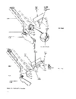
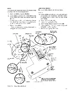
Страница 77: ...PT RT RELAY POTENTI OMETERS THERMAL RESET Figure 7 6 14U2 Model i Hear View 7 6 N...

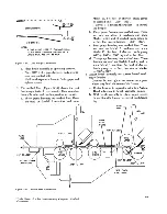
Страница 78: ...PKT 1 8 Figure 7 7 1402 Card Transport PUNCH CHECK BRUSHES READ SYNC SWITCH ERF AND MODEL 3 7 7...

Страница 79: ...d Feed Roll Assembly Gage This gage is used for timing the first and second stepped feed rolls Read Clutch Locating Plate Gage This gage establishes the correct relationship between the center plate a...

Страница 80: ...S231 0002 5 t J I s J 0 tv 0 S 1 Po S C v CIl tv W 6 0 0 tv V t TIrn International Business Machines Corporation Data Processing Division 112 East Post Road White Plains N Y 10601...

Отзывы: