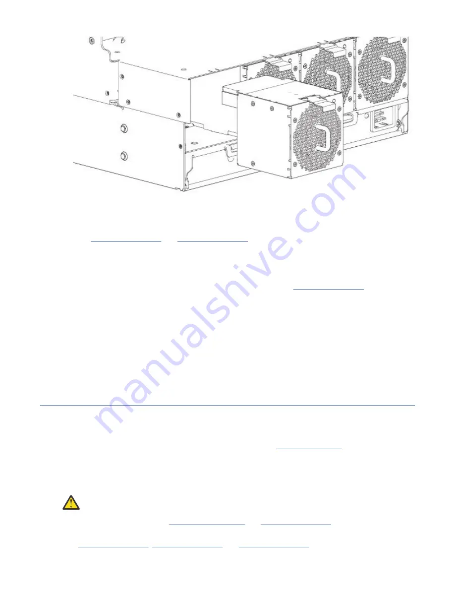
Figure 64. Removing a system fan (2 of 2)
Installing a system fan module
Refer to Figure 63 on page 71 and Figure 64 on page 72 when performing this procedure, but ignore the
directional arrow—since you will insert the module into the slot—rather than remove it.
Important: Handle the system fan carefully, and avoid damaging connectors.
1. Check for damage, especially to all module connectors.
2. Align the system fan module for insertion into its slot, as shown in Figure 64 on page 72.
3. Insert the system fan, and slide the module into the enclosure, taking care to support the base and
weight of the module with both hands.
Gently, but firmly, push the fan module into its fully seated position with its mating connector in the
enclosure.
4. Verify that the System Fan Status LED is off. Verify that the cooling fans are spinning with no fail states.
Verify that the front panel LED states show no amber module faults.
5. If replacing multiple fans, repeat steps 1 through 4. The replacement procedure should be completed
within an absolute maximum of 2 minutes for this CRU module.
Replacing a controller fan module
This section provides procedures for replacing a failed controller fan module.
Illustrations in controller fan replacement procedures show top panel views of the enclosure, with the fan
properly oriented for insertion into top panel of the enclosure, near the IOMs/EBOD expander modules.
Remove the top lid “B” to access the controller module fan. See Figure 9 on page 12. Re-attach top lid
“B” when you complete the procedure.
If a system fan module fails, the remaining fan is sufficient to maintain operation of the enclosure. You
need not halt operations and completely power-off the enclosure when replacing only one controller
module fan.
CAUTION: Do not remove the cover from the controller fan module due to danger from electric
shock inside. Return the module to your supplier for repair.
See CAUTION bullets regarding electrostatic discharge and anti-static protection.
Tip: The illustrations show controller fan module replacement as you face the enclosure rear panel. See
also Figure 11 on page 13, Figure 20 on page 23 and Figure 21 on page 24.
72 IBM ESS expansion: Hardware Installation and Maintenance Guide - Model 106
Содержание 106
Страница 1: ...IBM ESS expansion Version 5 3 5 Hardware Installation and Maintenance Guide Model 106 IBM SC27921101...
Страница 6: ...Russia Electromagnetic Interference Class A Statement 100 Homologation statement 100 vi...
Страница 12: ...xii...
Страница 18: ...xviii IBM ESS expansion Hardware Installation and Maintenance Guide Model 106...
Страница 20: ...2 IBM ESS expansion Hardware Installation and Maintenance Guide Model 106...
Страница 44: ...26 IBM ESS expansion Hardware Installation and Maintenance Guide Model 106...
Страница 53: ...Figure 28 CMA attachment aligned with outer slide Figure 29 Panhead screws Chapter 4 Installation 35...
Страница 84: ...66 IBM ESS expansion Hardware Installation and Maintenance Guide Model 106...
Страница 100: ...82 IBM ESS expansion Hardware Installation and Maintenance Guide Model 106...
Страница 108: ...90 IBM ESS expansion Hardware Installation and Maintenance Guide Model 106...
Страница 119: ......
Страница 120: ...IBM SC27921101...


