Power cord connection
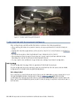
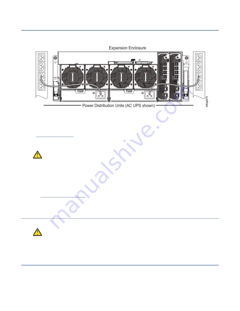
Connect a power cord from each PSU on the enclosure rear panel to the PDU (power distribution unit) as
shown in the illustration below.
Figure 59. Typical AC power cord connection from PDU to PSU
Important: The Model 106 enclosure is fitted with two redundant PSUs. All power cords must be
connected to at least two separate and independent power supplies to ensure redundancy.
• Figure 59 on page 52 shows power connection from a single-core PSU to a PDU using C19 connectors.
• The C20 plug on the PSU connects to the C19 receptacle of the power cord. The C20 plug on the power
cord connects to the C19 receptacle in the PDU.
CAUTION: Power connection concerns:
• Never connect the power cord to the PSU before installing the PSU in the system.
• Always remove the power connections before you remove the PSU from the enclosure.
• Whether standard (single-lead) or bifurcated (Y-lead), power cords must only be connected to a
supply range of 200–240V AC as indicated on each PSU’s hazardous voltage warning label.
Testing enclosure connections
See Powering on/powering off. Once the power-on sequence succeeds, the storage system is ready to be
connected.
Grounding checks
The product must only be connected to a power source that has a safety electrical earth connection.
CAUTION: If more than one enclosure goes in a rack, the importance of the earth connection to
the rack increases because the rack will have a larger Earth Leakage Current (Touch Current).
Examine the earth connection to the rack before power on. An electrical engineer who is qualified to the
appropriate local and national standards must do the examination.
Updating firmware
See the mmchfirmware command for managing the enclosure and drive firmware.
52 IBM ESS expansion: Hardware Installation and Maintenance Guide - Model 106
Содержание 106
Страница 1: ...IBM ESS expansion Version 5 3 5 Hardware Installation and Maintenance Guide Model 106 IBM SC27921101...
Страница 6: ...Russia Electromagnetic Interference Class A Statement 100 Homologation statement 100 vi...
Страница 12: ...xii...
Страница 18: ...xviii IBM ESS expansion Hardware Installation and Maintenance Guide Model 106...
Страница 20: ...2 IBM ESS expansion Hardware Installation and Maintenance Guide Model 106...
Страница 44: ...26 IBM ESS expansion Hardware Installation and Maintenance Guide Model 106...
Страница 53: ...Figure 28 CMA attachment aligned with outer slide Figure 29 Panhead screws Chapter 4 Installation 35...
Страница 84: ...66 IBM ESS expansion Hardware Installation and Maintenance Guide Model 106...
Страница 100: ...82 IBM ESS expansion Hardware Installation and Maintenance Guide Model 106...
Страница 108: ...90 IBM ESS expansion Hardware Installation and Maintenance Guide Model 106...
Страница 119: ......
Страница 120: ...IBM SC27921101...


