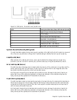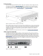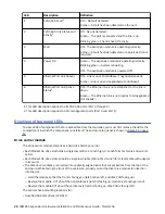
LED
Description
Definition
1
12Gb SAS Fault
1
Off — No fault detected.
Amber— A fault has been detected on the port.
2
12Gb SAS Link Status and
Activity
1
Off - No link detected.
Green — The port is connected and the link is up.
Blinking green - The link has I/O activity.
3
Fault
Off— The expansion module is operating normally.
Amber— A fault has been detected or a service action is
required.
4
Power OK
Green — The expansion module is operating normally.
Blinking green — System is booting.
Off— The expansion module is powered off.
5
Ethernet Port Link Speed
2
Off— Link is up at 10/100Base-T negotiated speeds.
Amber— Link is up and negotiated at 1000base-T.
6
Ethernet Port Link/Active
Status
2
Off— The Ethernet link is not established, or the link is
down.
Green — The Ethernet link is up (applies to all negotiated
link speeds).
1. This LED description applies to all 12Gb SAS ports (Port 0 through 3)
2. This LED description applies to both management ports (Port 0 and Port 1)
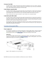
Overview of top panel LEDs
To view LEDs of components that are accessible from the top panel, you must first remove the lid for the
12.
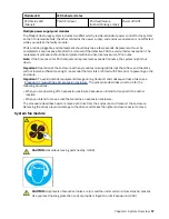
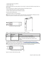
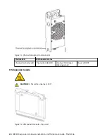
Drive carrier module
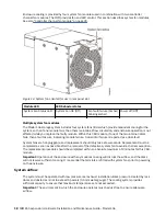
The drive carrier module comprises a hard disk held by a carrier.
• Each Model 106 drive slot holds a single low profile 1.0-inch high, 3.5-inch form factor disk drive in its
carrier.
• Each Model 106 drive slot can hold a single low profile (5/8-inch) 2.5-inch form factor disk with adapter
in its carrier.
• The disk drive modules are inserted into vertically aligned slots that are accessible from the top of the
enclosure. While facing the front of the enclosure, properly orient the disk drive module for insertion
into the slot:
– Hold the module so that the front is facing you (latch tab on left, and disk PCB facing up).
– Revolve the module -90º about the horizontal axis (latch is facing up, module is standing on end).
– Revolve the module 90º about the vertical axis (latch is facing up, disk PCB is facing left).
The carriers have mounting locations for:
• Qualified SAS disk drives (LFF/SFF).
20 IBM ESS expansion: Hardware Installation and Maintenance Guide - Model 106
Содержание 106
Страница 1: ...IBM ESS expansion Version 5 3 5 Hardware Installation and Maintenance Guide Model 106 IBM SC27921101...
Страница 6: ...Russia Electromagnetic Interference Class A Statement 100 Homologation statement 100 vi...
Страница 12: ...xii...
Страница 18: ...xviii IBM ESS expansion Hardware Installation and Maintenance Guide Model 106...
Страница 20: ...2 IBM ESS expansion Hardware Installation and Maintenance Guide Model 106...
Страница 44: ...26 IBM ESS expansion Hardware Installation and Maintenance Guide Model 106...
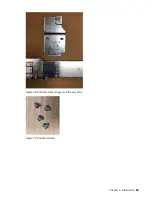
Страница 53: ...Figure 28 CMA attachment aligned with outer slide Figure 29 Panhead screws Chapter 4 Installation 35...
Страница 84: ...66 IBM ESS expansion Hardware Installation and Maintenance Guide Model 106...
Страница 100: ...82 IBM ESS expansion Hardware Installation and Maintenance Guide Model 106...
Страница 108: ...90 IBM ESS expansion Hardware Installation and Maintenance Guide Model 106...
Страница 119: ......
Страница 120: ...IBM SC27921101...


