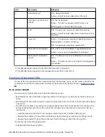
Firmware Fault LED
The LED illuminates amber when experiencing a firmware application fault such as a firmware upgrade
failure or memory corruption. This LED is normally off, and illuminates only when firmware-related fault
occurs. See troubleshooting procedures if this fault displays.
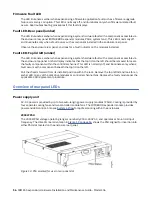
Fault LED–Rear panel (amber)
The LED illuminates amber when experiencing a system hardware fault with a component accessible via
the enclosure rear panel (IOMs/EBOD expander modules, PSUs, system fans). This LED is normally off,
and illuminates only when a fault occurs with a component installed in the enclosure rear panel.
Observe the enclosure rear panel, and look for a fault indicator on the modules installed.
Fault LED–Top lid left (amber)
The LED illuminates amber when experiencing a system hardware fault with a component accessible via
the enclosure top panel. Amber display indicates that the top lid on the left should be removed to locate
the faulty component within the controller channel. This LED is normally off, and illuminates only when a
fault occurs with a component beneath the top lid on the left.
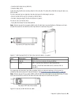
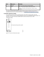
Pull the chassis forward from its installed position within the rack. Remove the top left lid and look for an
amber LED on any of the disk drive modules or controller channel fans. Replace the faulty module per the
applicable CRU replacement procedure.
Overview of rear panel LEDs
Power supply unit
AC-DC power is provided by up to two auto-ranging power supply modules (PSUs). Cooling is provided by
four separate cooling fans and two controller module fans. The IOM/EBOD expander module provides
power and LED control. Also see System airflow for optimal cooling within the enclosures.
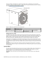
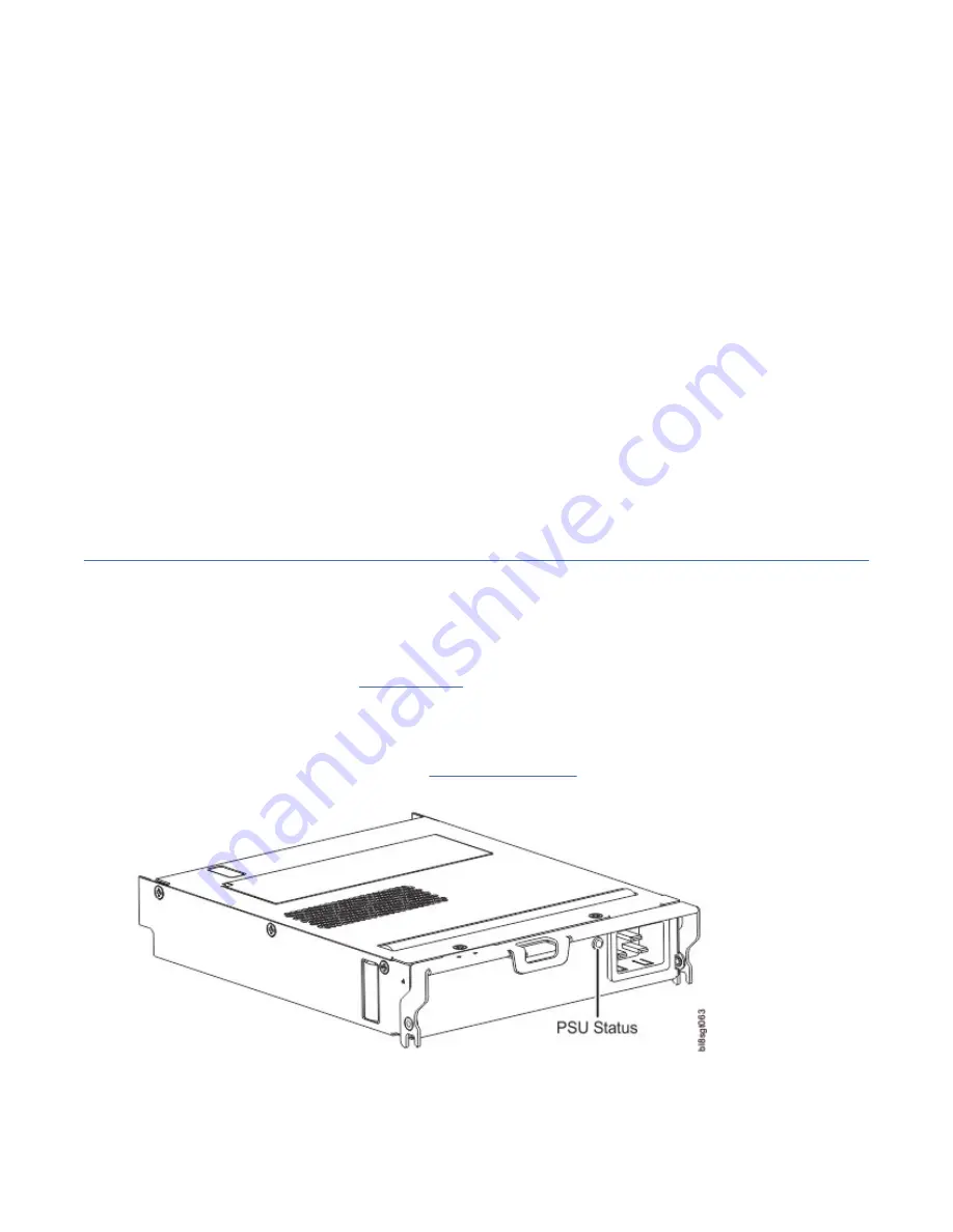
2000W PSU
The 2000W PSU voltage operating range is nominally 200V–240V AC, and operates at 50–60 Hz input
either PSU slot located on the enclosure rear panel.
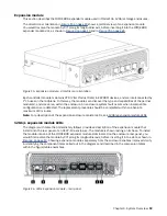
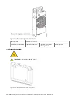
Figure 13. PSU oriented for use in rear panel slot
16 IBM ESS expansion: Hardware Installation and Maintenance Guide - Model 106
Содержание 106
Страница 1: ...IBM ESS expansion Version 5 3 5 Hardware Installation and Maintenance Guide Model 106 IBM SC27921101...
Страница 6: ...Russia Electromagnetic Interference Class A Statement 100 Homologation statement 100 vi...
Страница 12: ...xii...
Страница 18: ...xviii IBM ESS expansion Hardware Installation and Maintenance Guide Model 106...
Страница 20: ...2 IBM ESS expansion Hardware Installation and Maintenance Guide Model 106...
Страница 44: ...26 IBM ESS expansion Hardware Installation and Maintenance Guide Model 106...
Страница 53: ...Figure 28 CMA attachment aligned with outer slide Figure 29 Panhead screws Chapter 4 Installation 35...
Страница 84: ...66 IBM ESS expansion Hardware Installation and Maintenance Guide Model 106...
Страница 100: ...82 IBM ESS expansion Hardware Installation and Maintenance Guide Model 106...
Страница 108: ...90 IBM ESS expansion Hardware Installation and Maintenance Guide Model 106...
Страница 119: ......
Страница 120: ...IBM SC27921101...


