background image


ACO23/ACO234  Page 6 


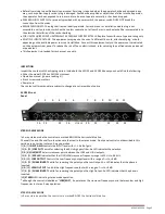
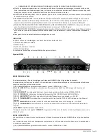
The ACO23 is marked in a similar way: for stereo 2-way operation use the markings above the connectors. To operate 
the ACO23 in mono 3-way mode

,

 use the markings below the connectors. The connectors which are not used in the 

selected mode are marked “not used”. This designation applies only to 

that mode 

of operation. 


ACO234 AUDIO CONNECTIONS 

• Before connecting anything to the crossover, make sure it is not connected to any power source.


• Be sure that the source device (equalizer, compressor, mixing console, etc.)

 for the ACO234-ACO23 is turned off. 

Connect the output(s) of the source device to the inputs of the crossover, following the rear panel

 markings carefully. 

• Make sure that the amplifiers which will be used to drive your speaker system are turned off. 

Using the back panel 

markings as a guide, use high quality cables to connect the amplifiers to the appropriate outputs of the ACO234

-ACO23. 


ELECTRICAL CONNECTIONS 

Ensure that your ACO234-ACO23 crossover conforms to the AC power specifications in your area

, by checking the 

marked voltage spec on the rear of the unit. Never plug the incorrect voltage into your crossover, as this may cause 

severe damage not covered under the warranty. Connect the power cord to the crossover first, then to a power source 

that is properly grounded. Never lift the ground as a shock hazard may result. 

After you have safely plugged in the crossover, turn on the source device(s). Turn the amplifiers’ outputs all the way 

down (-

∞) and turn on the amplifiers. All of the elements of your sound system should now be on, and the amplifiers 

should be turned all the way down. Turn the source device to its nominal operating level, sending a nominal (average) 

level to the ACO234-ACO23. Slowly turn up the amplifiers’ outputs until you can hear signal at a comfortable volume. 

Make adjustments as you desire. 


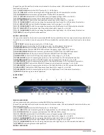
X10 SWITCH 

If you are using your system in stereo 2

-way or 3-

way mode, the needed crossover frequency may be higher than 960 

Hz, making it necessary to set the x10 switch to the active positi

on. This changes the range of operation of the 

frequency selector from 45

-

960 Hz to 450 Hz to 9.6 kHz. All other frequency selectors remain the same. When using the 

X10 switch, ALWAYS ensure that the amplifiers feeding all speaker systems are turned off or

 that the input gain controls 

on the power amplifiers are turned down before changing the setting of the X10 switch. Not doing so may send a 

spurious signal to the outputs of the crossover when the X10 switch is engaged, and may damage speaker systems 

which are powered at the time of the spurious signal. 


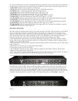
POLARITY SWITCH 

Every output is equipped with a polarity (Ø) reverse switch on the front


panel. When speakers are not “in phase”, the 

frequency response of the


system is compromised, particularly in the low frequencies. Out of phase

 signals can also 

cause “comb-

filtering” in the high frequencies. The polarity

 switch is extremely useful for fine tuning your sound system 

for peak performance. An LED is activated when the output polarity is reversed. 


LOW FREQUENCY SUMMING 

The other feature accessed on the back panel is “low frequency summing”.

 This is useful with systems that utilize mono 

subwoofers. 

Activating the LF sum switch “sums” the low frequencies of both the left

 and right inputs. The sum is sent 

to channel one’s low output marked “LF 

SUM”, while channel two’s low output is not used, and channel two’s

 phase 

invert led is disabled, indicating it is not operational in “LF Sum”


mode. The summed low frequencies represent all the 

low frequencies of

 both t

he left and right inputs, and since lows are generally non

-

directional anyway, it will not detract 

from the true stereo picture of the source material. 


RACK MOUNTING, GROUNDING & SAFETY 

We have provided 4 rack screws and washers for easy mounting in standard audio racks. You should avoid mounting 

the unit near large power transformers or motors. Route the AC cord away from audio lines and plug it into a power 

source close by. If the power cord must cross over


audio lines, you should take care to have 

them cross at 90 degree 

angles. The input and output connectors are balanced/unbalanced 1/ 4” TRS type connectors. The tip of the plug is 

wired as hot (+), the ring is wired

 as cold (-

), and the sleeve is wired as the ground or shield.


The ACO234-ACO23 crossovers have differentially balanced input 

and output circuits. Balanced wiring is recommended, 

even with unbalanced 

source devices, especially when running long paths. Twin

-

conductor,

 shielded cable is more 

reliable since it does not depend on the shield wire itself to complete the signal connection. Using twin conductor 

cable,

 a broken shield may only result in a slight increase in noise or hum due to the lack of shielding. You may also use 

unbalanced cables to connect to and from the crossover.

Содержание ACO23

Страница 1: ...TIVE STEREO CROSSOVER FILTRE ACTIF STEREO CROSSOVER STEREO ACTIVO FILTRU ACTIV STEREO ACO23 2 WAY STEREO 3 WAY MONO ACO234 2 3 WAY STEREO 4 WAY MONO USER MANUAL MANUEL D UTILISATION MANUAL DE INSTRU E...

Страница 2: ...is necessary for the user to refer to the owner s manual These symbols warn that there are no user serviceable parts inside the unit Do not open the unit Do not attempt to service the unit yourself R...

Страница 3: ...ou should find the following Either the model ACO23 or ACO234 crossover Operation manual you are reading it 4 rack screws and washers Power cord The contents of this manual are subject to change at an...

Страница 4: ...nt between LOW MID and HIGH MID frequencies 9 HIGH MID HIGH Selects the crossover point between HIGH MID and HIGH frequencies 4 LOW OUTPUT Controls the LOW frequency output level with a range of to 6...

Страница 5: ...improperly setup or the switches were mistakenly pushed during the regular operation of a sound system Therefore great care should be taken when setting these switches There is a mode diagram on the...

Страница 6: ...t the input gain controls on the power amplifiers are turned down before changing the setting of the X10 switch Not doing so may send a spurious signal to the outputs of the crossover when the X10 swi...

Страница 7: ...o grounds of the devices in the signal path Remember for safety you must maintain connection to chassis ground Never lift a safety ground If you suspect the hum is not caused by a ground loop Check th...

Страница 8: ...Panel Low Cut Activates 40 Hz Butterworth 12 dB octave high pass filter one switch per channel Phase Invert Inverts the phase at the output one switch per output Rear Panel x10 Multiplies crossover fr...

Страница 9: ...point d exclamation dans un triangle attire l attention de l utilisateur sur des informations importantes contenues dans le mode d emploi Ces symboles signifient que l appareil ne contient aucune pi c...

Страница 10: ...rdon d alimentation Le contenu de l emballage est susceptible de changer sans pr avis Fa ade ACO234 MODE STEREO A 2 VOIES Pour le mode st r o 2 voies les r glages sont marqu s EN DESSOUS de la ligne b...

Страница 11: ...Hz 9 6kHz 3 LOW MID HIGH MID D termine le point de s paration entre les fr quences BAS MEDIUMS et HAUT MEDIUMS 9 HIGH MID HIGH D termine le point de s paration entre les fr quences HAUT MEDIUMS ET HAU...

Страница 12: ...ner un des 3 modes de fonctionnement ACO234 ou 2 modes de fonctionnement ACO23 Les cons quences d une mauvaise installation ou d une manipulation accidentelle des commutateurs pendant le fonctionnemen...

Страница 13: ...e sonorisation doivent maintenant tre sous tension Tournez la source sur son niveau de fonctionnement normal en envoyant un niveau nominal moyen vers le filtre ACO234 ACO23 Montez lentement les sortie...

Страница 14: ...n d alimentation est correctement branch sur la fiche l arri re du filtre ainsi que sur une prise secteur aliment e en tension Si l appareil est aliment mais il n y a aucun son audible V rifiez que de...

Страница 15: ...t r o Grave aigu 45 960 Hz ou 450 Hz 9 6 kHz r glage x10 Grave m dium 45 960 Hz ou 450 Hz 9 6 kHz r glage x10 M dium Aigu 450 Hz 9 6 kHz ACO234 Mode Mono Bas bas m dium 45 960 Hz ou 450 Hz 9 6 kHz r g...

Страница 16: ...48 3cm x 17 5cm Poids ACO234 1 8 kg ACO 223 1 7 kg Poids brut ACO234 2 6 kg ACO 223 2 5 kg Note Sous reserve de modifications sans pr avis NOTE IMPORTANTE Les produits lectriques ne doivent pas tre m...

Страница 17: ...manual de instru es Estes s mbolos alertam de que n o h pe as de substitui o no interior da unidade N o abra a unidade N o tente reparar o aparelho autonomamente Consulte os servi os de profissionais...

Страница 18: ...l de instru es 4 Parafusos e anilhas para rack Cabo de alimenta o O conte do deste manual est sujeito a altera es sem aviso pr vio Painel Frontal ACO234 MODO STEREO 2 VIAS Em modo stereo de 2 vias os...

Страница 19: ...qu ncias HIGH MID e HIGH 4 LOW OUTPUT Controla o n vel de sa da de baixa frequ ncia com alcance de a 6 dB 15 PHASE INVERT Interruptor para inverter a polaridade de sa da baixa Um LED indica a selec o...

Страница 20: ...interruptores fossem indevidamente manuseados durante a opera o de um sistema de som Dever ter cuidado quando definir essas op es H um diagrama de modo no painel traseiro de modo a ajudar a entender...

Страница 21: ...op o X10 certifique se sempre de que os amplificadores que alimentam os sistemas de som s o desligados ou que os controlos de entrada de gain dos amplificadores de pot ncia s o colocados no m nimo an...

Страница 22: ...correctas Verifique se as liga es do sinal de udio da linha de chassis e de pot ncia de todas as unidades do sistema est o ligadas Zumbido e ou Ru do Se suspeitar que o zumbido causado por um loop de...

Страница 23: ...e Filtro Linkwitz Riley 24 dB oitava varia o de estado FUN O DE INTERRUPTORES Painel Frontal Low Cut Activa 40 Hz Butterworth filtro high pass 12 dB oitava um interruptor por canal Inversor Phase Inve...

Страница 24: ...pecializat Deconectati aparatul de la retea in timpul furtunilor pentru a preveni deteriorarea INSTRUCTIUNI DE SIGURANTA AVERTISMENT ACEST APARAT TREBUIE SA FIE LEGAT LA PAMANTAREA DE PROTECTIE Daca p...

Страница 25: ...ecventa joasa LED ul indica faptul ca faza a fost inversata 6 12 IESIRE HIGH Controleaza nivelul iesirii frecventei inalte in intervalul cuprins intre to 6 dB 17 24 INVERSARE FAZA Comutator pentru inv...

Страница 26: ...intre pana la 6 dB 23 INVERSARE FAZA Comutator pentru inversarea polaritatii iesirii MEDII INALTE LED ul indica alegerea facuta 12 IESIRE HIGH Controleaza nivelul iesirii Frecventei INALTE cu interval...

Страница 27: ...gresit in timpul functionarii normale a sistemului de sunet Prin urmare trebuie sa aveti mare grija atunci cand setati aceste comutatoare Exista o diagrama pe panoul din spate pentru a va ajuta sa int...

Страница 28: ...ncet iesirile amplificatoarelor pana cand veti putea auzi semnalul la un volum confortabil Efectuati reglarile dupa cum doriti COMUTATOR X10 Daca utilizati sistemul dumneavoastra pe modul stereo 2 cai...

Страница 29: ...ire audio necorespunzatoare Asigurati va ca modul adecvat pentru configurarea dvs a fost selectat prin intermediul comutatoarelor din spatele panoului Verificati comutatorul LF Sum Verificati comutato...

Страница 30: ...IILE COMUTATOARELOR Panoul Fontal Low Cut Activeaza 40 Hz Butterworth 12 dB octave filtru inalte o comutare canal Inversare Faza Inverseaza faza la iesire o comutare iesire Panoul din spate x10 Multip...

Отзывы: