1-9
INSTALLATION
SL 80-399 MODULATING GAS BOILER
SL 26-260 G3, SL 40-399 G3 MODULATING GAS BOILERS
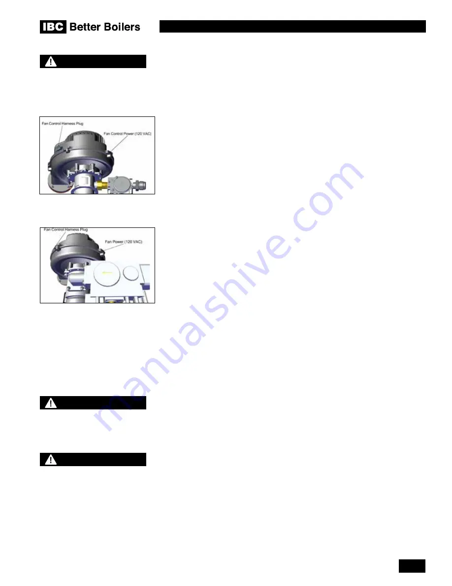
Figure 5A: 26-260 Fan control
harness plug
Figure 5B: 40-399 Fan control
harness plug
BEST PRACTICES
To reduce the possibility of
expansion noise, allow a 1/4” gap
around the exhaust and air intake
piping.
All vent connections must be liquid and pressure tight. Prior to firing the boiler, and before
any of the venting run is concealed by the building construction, the installer must test the
exhaust joints under fan pressure with the vent blocked, using a soap and water solution.
The installer must fill the condensate trap prior to testing.
To drive the fan into manual high speed operation for vent leak testing, unplug the
fan
control harness plug (see Figures 5A and 5B), and then block the vent outlet so that the
vent run will be under maximum fan pressure. Paint all joints with an approved leak test
solution just as you would joints in a gas line, and make sure there are no leaks. Good
practice would suggest that the installer attach a tag on the vent line near the condensate
drain tee indicating the type of test, the date and the installer’s name.
1.4.4 Venting Passage Through Ceiling and Floor
•
Confirm material meets local codes including fire stopping requirements.
• Some local jurisdictions require a minimum initial length of pipe be exposed or
accessible for inspection.
• Pipe clearances - no IBC requirements; follow local codes.
• All piping must be liquid and pressure tight.
1.4.5 Rooftop Vent Termination
a)
Rooftop vents must terminate as follows:
• The exhaust pipe can terminate in an open vertical orientation without concern about
rain infiltration; rain will drain away through the condensate trap.
•
Optional bird screen may be placed in a termination fitting. Leave unglued, and hold in
place with a short nipple. This permits easy access for cleaning.
• DO NOT exhaust vent into a common venting system.
b) For Rooftop Direct Vent systems:
•
Rooftop, two pipe, direct vent configurations, including typical clearance requirements,
are shown in Figure 8.
• The intake air pipe is not typically drained, so it must be terminated with a down-turned
elbow (see Figure 8).
• The intake pipe does not need to penetrate the roof at the same elevation as the
exhaust (as shown); lower down on the roof is acceptable.
• For roof top venting of multiple boiler sets, group all intake terminals together for a
common penetration through a custom cap. Alternatively, place in the closest proximity
achievable using commonly available pipe flashing. Similarly group the exhaust pipes
and place the two separate groups of pipes at least 3' apart (the closest intake and
exhaust pipes shall be 36", or more, apart). Use the same 12" (minimum) vertical
separation for all termination options. For alternate group terminations, contact the IBC
Factory for written guidance.
• Roof Top Concentric Termination kits are approved for use with the boiler model. The
installation of the vertical roof top concentric termination must follow the installation
instructions supplied with the venting material manufacturer. Care must be taken to
install the termination kit a minimum horizontal distance of 10’ (305cm) away from
any portion of the building and a minimum of 2’ (61cm) above the roof line plus the
anticipated snow line.
WARNING
Follow all installation
instructions supplied by the pipe
and fitting manufacturer.
WARNING
Condensate can cause corrosion
of metal roofing components
and other roofing materials.
Check with the builder or
roofing contractor to ensure
that materials will be resistant to
acidic condensate. pH levels can
be as low as 3.0


