background image


3-- Operation 


Viewing Page 

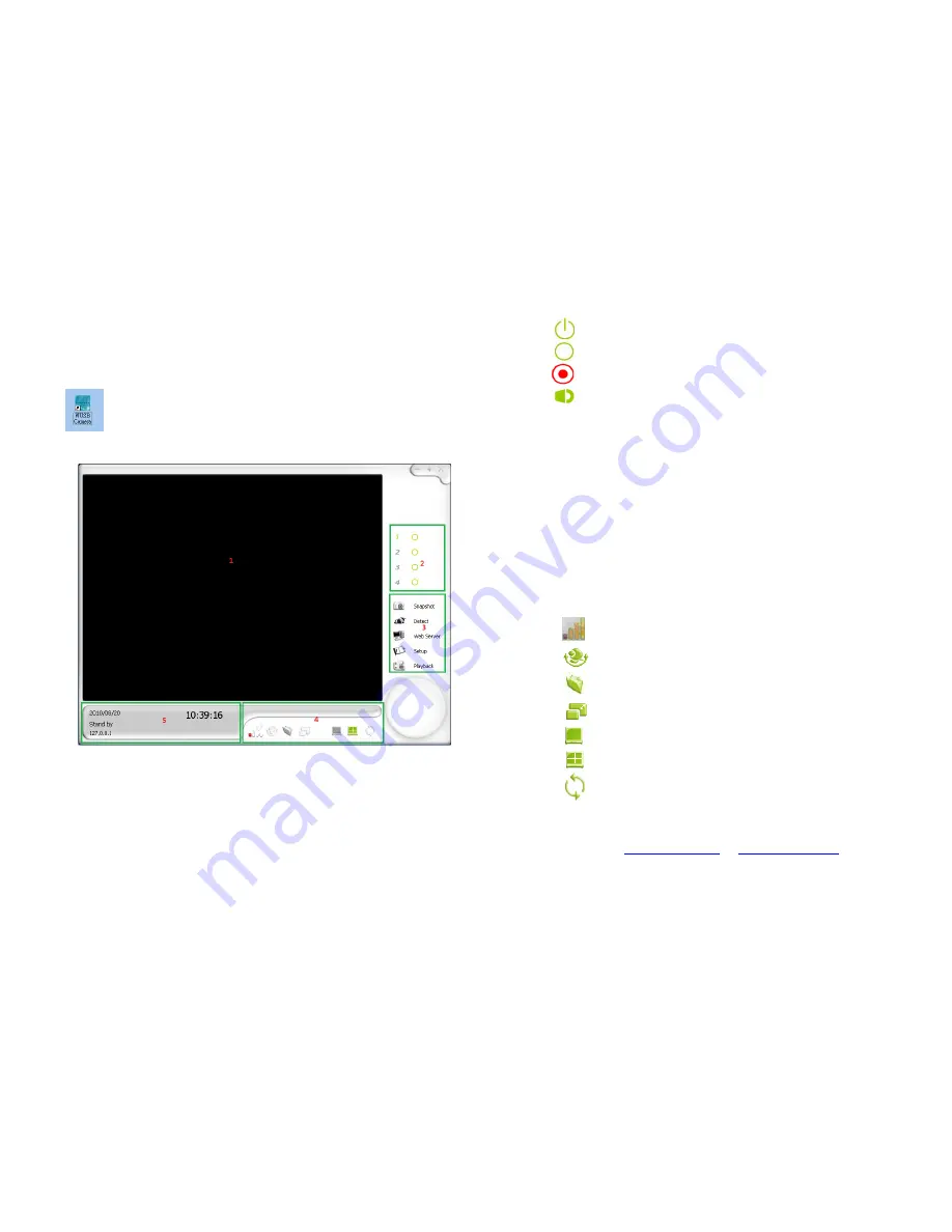
Insert the USB Receiver to one USB port of PC and double-click   

  on the desktop, the viewer screen will display as shown below 


Main Screen 


  then turn on the camera. 


1. 

Monitoring Screen:


This will display the camera’s view.   

Depending on the configuration, you can have different type of viewing 
methods on this screen. 

2. 

Channel Status:


This will display the status of each individual 

camera. 


  :   

This icon indicates that the camera is monitoring 


  :   

This icon indicates that the camera is in standby 

mode 


  :   

This icon indicates that the camera is recording 


  :   

This icon indicates that the camera’s audio is enabled 


3. 

Option Menu:


This area allows you to do the following: 


Snapshot: 

  Built-in snapshot function allows user to capture 

        images they would like 


Detect:

    Controls the view to go into detection mode or standby 

        mode 


Web Server:

    Enables web server mode for remote viewer 


Setup: 

  This system built-in web interface offers more advanced 


  settings.    On the viewing page, click the SETUP icon to enter 

server settings page.    It is a toggle button to switch between config 
and view pages. 


Playback

:    Enters the playback mode to view recorded videos   


4. 

Camera/Screen Control:


This area controls the following: 


:


  Displays the signal strength of wireless cameras 


:


Cruise camera to let it automatically move on its own 


:


Opens the snapshot folders to view captured pictures 


:


Adjusts the screen size on the monitoring screen 


:


Displays one channel on the monitoring screen


:


Displays multiple channels on the monitoring screen 


:


Cycles the camera to see all area 


Copy Right 

© 

IA Technologies    02/23/2011                           


Webpage :   

www.iat101.com

 ;   

www.ia-tecs.com


Содержание Mini Portable Wireless NVR System

Страница 1: ...or replacement in case of defects in material and workmanship In such cases the defective unit will be repaired or replaced by the manufacturer This warranty does not cover damages caused by improper...

Страница 2: ...receiver Connect the equipment into an outlet on a circuit different from that to which the receiver is connected Consult the dealer or an experienced radio TV technician for help FCC Caution To assur...

Страница 3: ...nd unplug the power cord it may result product malfunction Do not install the product in an environment where the humidity is high Unless the product is waterproof or weatherproof otherwise poor image...

Страница 4: ...Supplied Software 6 3 Operation 7 Viewing Page 7 Pairing 8 System Setting 9 Remote Monitoring 10 Basic Setting 10 Image Adjust 11 Record Setting 11 Motion Detect 14 Alert Setting 15 Play Back 15 Appe...

Страница 5: ...2000 XP Vista or Window 7 Windows Media Player 9 or higher recommended One available USB port CD ROM Drive For software installation Noun Definition IP Address Setting IP Assignment Camera Network Con...

Страница 6: ...n be stuck in a discreet location Put down the camera s stand The camera can be placed on a platform Copy Right IA Technologies 02 23 2011 Webpage www iat101 com www ia tecs com Ceiling Wall installat...

Страница 7: ...rations Move the camera to make adjustment To keep the USB receiver position above the desktop for best result You can connect USB receiver to the USB extension cable supplied to adjust the position o...

Страница 8: ...tion allows user to capture images they would like Detect Controls the view to go into detection mode or standby mode Web Server Enables web server mode for remote viewer Setup This system built in we...

Страница 9: ...amera which you want to match then press and hold the pairing button on the side of the camera for about 6 seconds If the pairing is successful you can find Match complete a camera had been connected...

Страница 10: ...details are clearly shown IP address The IP address of the web service for the viewer This system will log automatically the IP location of where the current computers If you use a router or dynamic...

Страница 11: ...ologies 02 23 2011 Webpage www iat101 com www ia tecs com Basic Settings This section of the wireless network camera system viewer allows users to display custom information on the main screen Channel...

Страница 12: ...fine tune the rotation angle and then display the rotate dynamic image Source Adjustment Adjust video parameters to process brightness saturation and gamma Record Setting This section sets up how reco...

Страница 13: ...below images Select Periodically 1 Setup the start date and time of Scheduling Type Periodically 2 Setup the end date and time of Scheduling Type Periodically Select Daily 1 Setup the start time of Sc...

Страница 14: ...of weekly Scheduling Select Monthly 1 Choose the start time of Scheduling Type Monthly 2 Choose the end tine of Scheduling Type Monthly 3 Select the icon Operative Period to specific period 4 Select...

Страница 15: ...created detection blocks Add new area Select the icon Add new Area to add new area to detect do this by holding down the right mouse button over the displayed screen area to create a new block Delete...

Страница 16: ...e recorded videos Press the Playback on the main screen 1 Main display screen This area will display the video output from the recording 2 Intelligent search not available 3 Time and channel selection...

Страница 17: ...can t preview the image of the camera from other PCs Please check if the local area connection has the firewall blocking that particular program and that the IP address is correct What does Can not co...

Страница 18: ...life this product should not be treated as household or general waste It should be handed over to the applicable collection point for the recycling of electrical and electronic equipment or returned...

Отзывы: