

Operation Pattern
Description
Example for Electric Cylinder Connection
Example for Air Cylinder Connection
(Reference)
PIO Pattern 2
Double Solenoid
System
(Point-to-Point
Movement, Target
Position Setting
(Position Data)
Change)
The pressing operation is available.
+24V
PLC
Backward Position
Movement Signal
(ST0)
Forward Position
Movement Signal
(ST1 )
Target Position
Change Signal
(CN1)
Backward
Position Detection
(LS0)
Forward
Position Detection
(LS1)
Dedicated
Cable
Electric Cylinder
MSEP
R2
R1
B
A
Air Cylinder
PLC
P(Air)
P(Air)
Backward Position
Movement Signal
(ST0)
Forward Position
Movement Signal
(ST1 )
Target Position
Change Signal
(CN1)
Backward
Position Detection
(LS0)
Forward
Position Detection
(LS1)
PIO Pattern 3
(2-Input, 3-Point
Movement)
The actuator 3-Point Movement is
available using the same control
function as for the air cylinder.
The target position setting (forward
position, backward position and
intermediate position) is available.
Speed and acceleration settings in the
actuator movement are available.
Pressing operation is available at the
points except for the intermediate point.
+24V
PLC
Movement
Signal 1
(ST0)
Movement
Signal 2
(ST1 )
Backward
Position Detection
(LS0)
Forward
Position Detection
(LS1)
Intermediate
Position Detection
(LS2)
Dedicated
Cable
Electric Cylinder
MSEP
Air Cylinder
PLC
P(Air)
P(Air)
P(Air)
Movement
Signal 1
(ST0)
Movement
Signal 2
(ST1 )
Backward
Position Detection
(LS0)
Forward
Position Detection
(LS1)
Intermediate
Position Detection
(LS2)
PIO Pattern 4
(3-Input, 3-Point
Movement)
The actuator 3-Point Movement is
available using the same control
function as for the air cylinder.
The target position setting (forward
position, backward position and
intermediate position) is available.
Speed and acceleration settings in the
actuator movement are available.
Pressing operation is available at the
points except for the intermediate point.
+24V
Dedicated
Cable
PLC
Electric Cylinder
Intermediate Position
Movement Signal
(ST2)
Backward Position
Movement Signal
(ST0)
Forward Position
Movement Signal
(ST1)
Backward
Position Detection
(LS0)
Forward
Position Detection
(LS1)
Intermediate
Position Detection
(LS2)
MSEP
Air Cylinder
PLC
P(Air)
P(Air)
P(Air)
Intermediate Position
Movement Signal
(ST2)
Backward Position
Movement Signal
(ST0)
Forward Position
Movement Signal
(ST1)
Backward
Position Detection
(LS0)
Forward
Position Detection
(LS1)
Intermediate
Position Detection
(LS2)
PIO Pattern 5
(Continuous
Reciprocating
Operation)
The actuator’s point-to- point
reciprocating operation is performed
between the forward position and
backward position.
The target position setting (forward
position and backward position) is
available.
Speed and acceleration settings in the
actuator movement are available.
The pressing operation is available.
+24V
PLC
Continuous
Reciprocating
Operation Signal
(ASTR)
Backward
Position Detection
(LS0)
Forward
Position Detection
(LS1)
Dedicated
Cable
Electric Cylinder
MSEP
●
Operation Patterns for Fieldbus Type
Operation
Pattern
Description Overview
Positioner 1/
Simple
Direct Mode
In Positioner 1 Mode, 256 points of
position data can be registered at the
maximum and is able to stop at the
registered positions. Monitoring of the
current position is also available.
In Simple Direct Mode, the target
position can be indicated directly by
inputting a value. Monitoring of the
current position is also available.
Communication with Fieldbus
Dedicated Cable
+24V
Target Position
Target Position No.
Control Signal
PLC
Current Position
Completed Position No.
Status Signal
Electric Cylinder
Direct
Numeric
Specification
Mode
The target position, speed
acceleration/deceleration and pressing
current limit can be indicated with
inputting a number. Monitoring of not
only the current position, but also the
current speed and indicated current are
available.
Communication with Fieldbus
+24V
Target Position
Positioning Width
Speed
Acceleration/Deceleration
Push %
Control Signal
PLC
Current Position
Current Value
(Command Value)
Current Speed
(Command Value)
Alarm Code
Status Signal
Dedicated Cable
Electric Cylinder
Positioner 2
Mode
This is the operation mode of the
position data of 256 points at maximum
set in the position table. The monitoring
of the current position is not available.
This mode is that the transferred data is
reduced from Positioner 1 Mode.
Communication with Fieldbus
+24V
Target Position No.
Control Signal
PLC
Completed Position No.
Status Signal
Dedicated Cable
Electric Cylinder
Positioner 3
Mode
This is the operation mode of the
position data of 256 points at maximum
set in the position table. The monitoring
of the current position is not available.
This is the mode to control with the
minimized number of signals to perform
the positioning operation by reducing
the amount of sent and received data
from Positioner 2 Mode.
Communication with Fieldbus
+24V
Target Position No.
Control Signal
PLC
Completed Position No.
Status Signal
Dedicated Cable
Electric Cylinder
SEP I/O
The same control as PIO is available.
Refer to PIO type
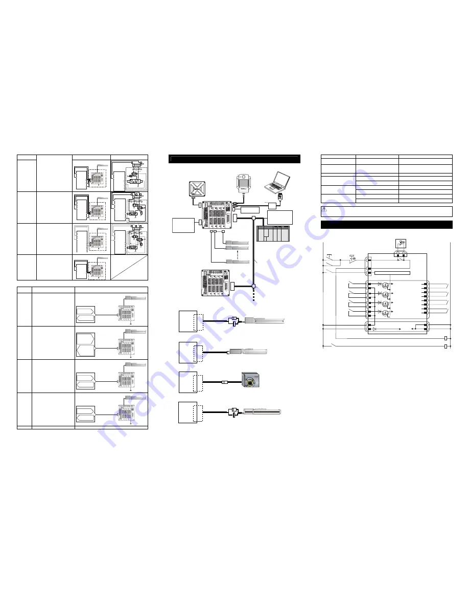
Wiring
1) Connection to RCP2 Series
2) Connection to RCP3, RCP4, RCP5, RCA2 RCD and RCL Series
3) Connection to RCP2 Small Rotary Series
4) Connection to RCA Series
Note 1 Connection Cable Model Codes
□□□
: Cable length Example) 030 = 3m
Model Cable
Remarks
RCP2
(Other than Small Rotary)
CB-PSEP-MPA
□□□
Robot cable from 0.5 to 20m
Small Rotary Type
RCP2-RTBL, RTCL, RTBSL,
RTCSL, RTBBL, RTCBL
CB-RPSEP-MPA
□□□
Robot cable from 0.5 to 20m
RCA CB-ASEP-MPA
□□□
Robot cable from 0.5 to 20m
CB-APSEP-MPA
□□□
Robot cable from 0.5 to 20m
RCP3, RCA2, RCL
CB-APSEP-MPA
□□□
-LC
Standard cable from 0.5 to 20m
CB-CA-MPA
□□□
-RB
Robot cable from 0.5 to 20m
RCP4 (Other than GR* Type),
RCD (Adaptation controller
symbol : D3)
CB-CA-MPA
□□□
Standard cable from 0.5 to 20m
CB-CAN-MPA
□□□
-RB
Robot cable from 0.5 to 20m
RCP4 (GR* Type), RCP5,
RCD (Adaptation controller
symbol : D5)
CB-CAN-MPA
□□□
Standard cable from 0.5 to 20m
Caution: Follow the content described in the model code record card inserted to the controller when connecting
actuators.
Wrong connection will issue an error such as the encoder wire breakage.
Power Supply and Emergency Stop Circuit
The following diagram shows an example of how the emergency stop switch for the teaching pendant may
be included in the emergency stop circuit you may construct.
EMGINSLOT0
EMGINSLOT1
EMGINSLOT2
EMGINSLOT3
Emergency Stop
Reset Switch
Emergency Stop
Switch
CR1
SIO Connector
CR1
24V
0V
Emergency Stop Control Circuit
Motor Power Supply (Slot 3)
(Axis No.6 and 7)
MPISLOT3
MPOSLOT3
CR2
(Note 2)
MPISLOT2
MPOSLOT2
CR2
(Note 2)
MPOSLOT1
MPISLOT1
CR2
(Note 2)
MPISLOT0
MPOSLOT0
CR2
(Note 2)
Motor Power Supply (Slot 2)
(Axis No.4 and 5)
Motor Power Supply (Slot 1)
(Axis No.2 and 3)
Motor Power Supply (Slot 0)
(Axis No.0 and 1)
MP+24V
0V
V
0
V
4
2
+
P
C
Control
Power
External Drive Cutoff •
Emergency Stop Input Connector
Power Line Input Connector
EMG+SLOT0
(Note 6)
S1
4
3
2
1
12
11
10
9
7
8
5
6
15
16
13
14
1
3
4
2
Emergency Stop Switch on
Teaching Pendant
S2
(Note1)
EMG A
EMG B
MSEP
8
5
EMG-
EMG+SLOT1
(Note 6)
EMG+SLOT2
(Note 6)
EMG+SLOT3
(Note 6)
3
2
4
CR1
(Note 4)
CR2
(Note 2)
CR1
System I/O Connector
Note 1 When the teaching pendant is not connected, S1 and S2 become short-circuited inside the controller.
Note 2 When the motor driving source is cut off externally for a compliance with the safety category, connect
a contact such as a contactor to the wires between MPISLOT* and MPOSLOT*.
Note 3 The rating for the emergency stop signal (EMG-) to turn ON/OFF at contact CR1 is 24V DC and
10mA.
Note 4 For CR1, select the one with coil current 0.1A or less.
Note 5 If supplying power with using a 24V DC, having it turned ON/OFF, keep the 0V connected and have
the +24V supplied/cut (cut one side only).
Note 6 By cutting out the connection between EMG+SLOT* and EMGINSLOT*, only the disconnected slot
number can be made in the condition of an emergency stop. (*: Slot Number)
MSEP
AX0 to 7
Actuator
Connector
MSEP
AX0 to 7
Actuator
Connector
MSEP
AX0 to 7
Actuator
Connector
MSEP
AX0 to 7
Actuator
Connector
Connection Cable
(Note 1)
Connection Cable
(Note 1)
Connection Cable
(Note 1)
Connection Cable
(Note 1)
Teaching Pendant
Touch Panel Teaching
(to be purchased separately)
Host System (Master Unit)
(PLC, etc.…Please prepare separately)
Communication power
supply (if necessary)
(24V DC
…Please prepare
separately)
Actuator
Emergency Stop
Circuit
Control/Drive Power
Supply
(24V DC
…Please prepare
separately)
PC software
(to be purchased separately)
Absolute Battery Box
Each Field Network
communication cable
Follow the specifications of
each Field Network for how to
lay out wiring.


