


Operation Mode Available
7 types of operation modes are available to select from. The settings are to be established with Gateway
Parameter Setting Tool.
Operation
Pattern
Contents Overview
Positioner
1
In Positioner 1 Mode, 256 points of
position data can be registered at the
maximum and is able to stop at the
registered positions. Monitoring of the
current position is also available.
Simple
Direct
Mode
In Simple Direct Mode, the target
position can be indicated directly by
inputting a value. Monitoring of the
current position is also available.
Those other than the target position
are to be indicated in the position
table, and the setting can be done for
256 points at maximum.
Communication with Fieldbus
Dedicated Cable
100V/200V AC
+24V
Target Position
Target Position No.
Control Signal
PLC
Current Position
Completed Position No.
Status Signal
Electric Cylinder
Direct
Indication
Mode
Direct
Indication
2 Mode
The target position, speed
acceleration/deceleration and
pressing current limit can be indicated
with inputting a number. Monitoring of
not only the current position, but also
the current speed and indicated
current are available.
In Direct Indication 2 Mode,
anti-vibration control is available
instead of JOG operation.
+24V
100V/200V AC
Target Position
Positioning Width
Speed
Acceleration/Deceleration
Push %
Control Signal
PLC
Current Position
Current Value
(Command Value)
Current Speed
(Command Value)
Alarm Code
Status Signal
Communication with Field Network
Dedicated Cable
Electric Cylinder
Position 2
Mode
This is the operation mode of the
position data of 256 points at
maximum set in the position table.
The monitoring of the current position
is not available
This mode is that the transferred data
is reduced from Positioner 1 Mode.
+24V
100V/200V AC
Target Position No.
Control Signal
PLC
Completed Position No.
Status Signal
Communication with Fieldbus
Dedicated Cable
Electric Cylinder
Position 3
Mode
This is the operation mode of the
position data of 256 points at
maximum set in the position table.
The monitoring of the current position
is not available
This is the mode to control with the
minimized number of signals to
perform the positioning operation by
reducing the amount of sent and
received data from Positioner 2 Mode.
+24V
100V/200V AC
Target Position No.
Control Signal
PLC
Completed Position No.
Status Signal
Communication with Fieldbus
Dedicated Cable
Electric Cylinder
Remote
I/O
Five types
(Note 1)
of control same for
PIO are available.
(Note 1) PIO patterns 0, 1, 2, 4 and
5 can be selected (by switching over
in driver board parameters).
+24V
100V/200V AC
Target Position No.
Control Signal
PLC
Completed Position No.
Status Signal
Communication with Fieldbus
Dedicated Cable
Electric Cylinder
Connection Diagram
Note 1 Applicable Moter Cable types
□□□
: cable length Example) 030 = 3m
Model Name
Cable
Reference
CB-RCC-MA
□□□
-RB
Robot cable from 0.5 to 20m
CB-RCC-MA
□□□
Standard cable from 0.5 to 20m
CB-X-MA
□□□
-RB
Robot cable from 0.5 to 20m
For Single Axis Robot
Connection
CB-X-MA
□□□
Standard cable from 0.5 to 20m
Note 2 Applicable Encoder Cable types
□□□
: cable length Example) 030 = 3m
Model Name
Cable
Reference
For Single Axis Robot
Connection
CB-X1-PA
□□□
Robot cable from 0.5 to 20m
For Connection of Single
Axis Robot Equipped with
LS (Option)
CB-X1-PLA
□□□
Robot cable from 0.5 to 20m
CB-X3-PA
□□□
Robot cable from 0.5 to 20m
For RCS2 [models
equipped with LS and
rotary models (RT*) are
excluded]
CB-RCS2-PA
□□□
Standard cable from 0.5 to 20m
CB-X2-PLA
□□□
Robot cable from 0.5 to 20m
RCS2 [for models
equipped with LS and
rotary models (RT*)]
CB-RCS2-PLA
□□□
Standard cable from 0.5 to 20m
CAUTION
The model code and the manufacturing number of the connected actuator are printed on MSCON front
panel. Check the information before connecting the actuator. Wrong connection will issue an error such
as the encoder wire breakage.
Power Line and Emergency Stop Circuit
<Drive (Motor) Power Supply Circuit>
<
Control Power Supply and Brake Power Supply Circuit>
<Emergency Stop Circuit>
It is the example of circuit layout when an emergency switch of the teaching pendant is used to the
emergency stop circuit of the equipment.
Note 1 When the teaching pendant is not connected, S1 and S2 become short-circuited inside the controller.
Note 2 When the motor power must be disconnected externally for safety category compliance, apply a
safety rated contactor between L and N.
Note 3 The rating for the emergency stop signal (EMG-) to turn ON/OFF at contact CR1 is 24V DC and
30mA.
Note 4 For CR1, select the one with coil current 0.1A or less.
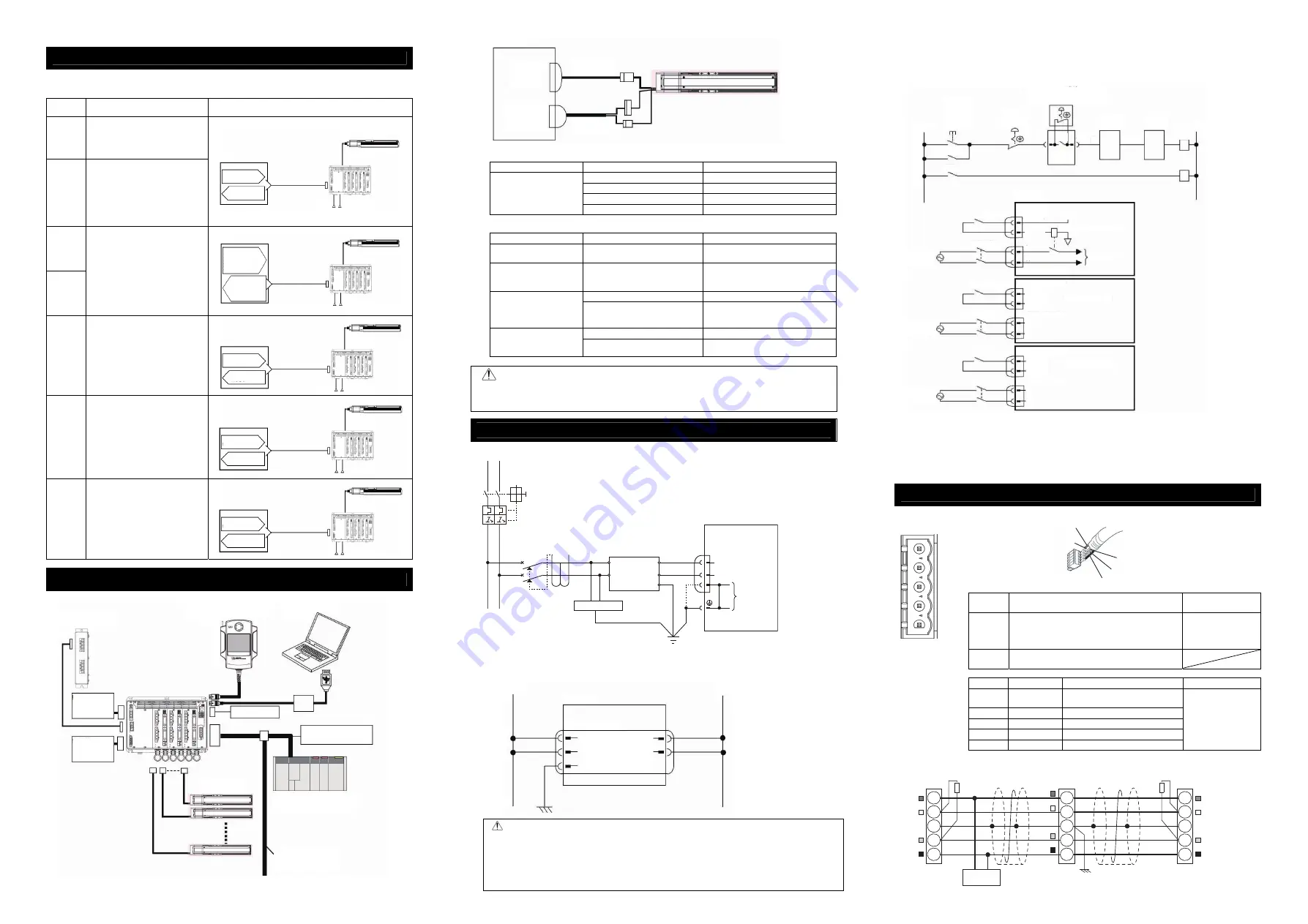
DeviceNet Type
Check the instruction manuals for each Field Network master unit and mounted PLC for the details.
Connector
Name
DeviceNet Connector
Cable
Side
SMSTB2.5/5-ST-5.08 AU
Enclosed in standard
package
Manufactured by
PHOENIX CONTACT
Controller
Side
MSTBA2.5/5-G-5.08 ABGY AU
Pin No.
Signal Name
Contents
Applicable Cable
1
V- (BK)
Power Supply Cable Negative
Side
2
CAN L (BL)
Communication Data Low Side
3
Shield (None) Shield
4
CAN H (WT)
Communication Data High Side
5
V+ (RD)
Power Supply Cable Positive Side
DeviceNet
Dedicated Cable
Caution
●
When using an actuator equipped with a brake, supply a brake power (24V DC).
With the power not being supplied, 0A5 Electromagnetic Brake Non-Release Error will occur. Do
not attempt to supply a brake power if there is no actuator with a brake.
●
If having the control power supplied/cut on the 24V DC side, keep the 0V connected and have the
+24V supplied/cut (cut one side only). If cut also on 0V side (cut both sides), it may damage the
internal circuit.
Teaching Pendant
Touch Panel Teaching
(to be purchased separately)
Host System (Master Unit)
(PLC, etc.…Please prepare separately)
Communication power supply
(if necessary) (24V DC…
Please prepare separately)
Actuator
Emergency Stop
Circuit
PC software
(to be purchased separately)
Regenerative Resistor Unit
Follow the specifications of each
Fieldbus for how to lay out wiring.
Control Power
Supply
(24V DC Please
prepare separately)
Drive Power Supply
(100/200V AC
Please prepare
separately)
MSCON
M0 to 5
Motor
Connector
PG0 to 5
Encoder
Connector
Motor Cable
(Note 1)
Encoder Cable
(Note 2)
L, N : AC100V or 200V (to be identified at order)
+24V
MSCON
0V
24V
+
FG
0V
-
Control Power
Supply Connector
Control Power Supply
Brake Power Supply
Shield
BL (CAN L)
RD (V+)
WT (CAN H)
BK (V-)
4
5
1
2
3
Front view of
connector on
controller side
MSCON
DeviceNet Type
V+
Drain
(Shield)
CAN_H
CAN_L
V-
RD
WT
BL
BK
RD
WT
BL
BK
V+
Drain
(Shield)
CAN_H
CAN_L
V+
Drain
(Shield)
CAN_H
CAN_L
V-
RD
WT
BL
BK
Communication power needs to be
supplied by an external device.
Connect the terminal resistor if the unit is
placed at the end of the network.
V-
Terminal Resistance
121
Ω
Terminal Resistance
121
Ω
24V
Power Supply
Class D grounding
(Formerly Class-III grounding : Grounding resistance at 100
Ω
or less)
Master Unit
Slave Device
L
Circuit
Breaker
Leak Current
Noise
Filter
Surge Absorber
MSCON
L
N
PE
(Earth on either
of them)
Class D grounding
(Formerly Class-III grounding:
Grounding resistance at 100
Ω
or less)
Motor Power Supply
Connector
Screw Terminal for
Protective Grounding
N
Emergency Stop
Reset Switch
Emergency
Stop Switch
Emergency stop switch
for the teaching pendant
(Note 1)
MSCON
Second Unit
MSCON
Second Unit
MSCON
nth Unit
+24V
CR1
S1
S2 S1
S2
S1
S2
MC1
EMG+
EMG-
+24V
L
N
CR
1
(Note 1)
CR1
(Note 3)
MC1
(Note 2)
CR1
(Note 3)
MC1
(Note 2)
CR1
(Note 3)
MC1
(Note 2)
CR1
(Note 1)
0V
MSCON
AC100V
AC200V
AC100V
AC200V
AC100V
AC200V
System I/O
Connector
System I/O Connector
Motor Power Cutoff Relay
Motor
Power Supply
Motor Power Input Connector
Motor Power Input Connector
EMG+
EMG-
L
N
MSCON Second Unit
System I/O Connector
Motor Power Input Connector
MSCON nth Unit
EMG+
EMG-
L
N


