


1.2 Mechanical specifications
1-13
1. Specifications
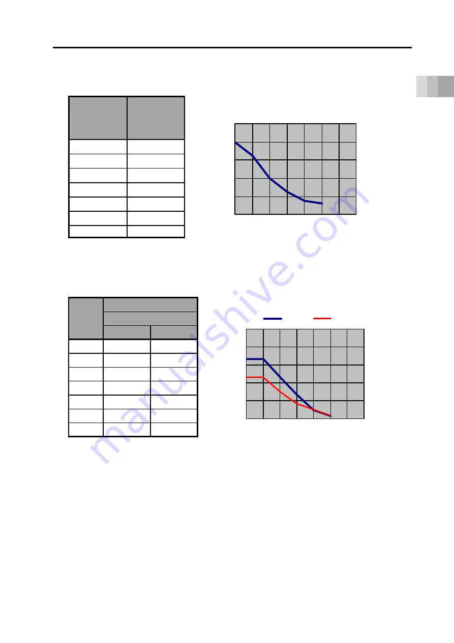
[Output torque
(Energy-saving: Enabled)
]
0
8.0
100
6.5
200
4.0
300
2.5
400
1.5
500
1.2
600
-
Speed
(deg./s)
Output torque
(N·m)
0.0
2.0
4.0
6.0
8.0
10.0
0 100 200 300 400 500 600 700
O
ut
put
tor
que
[N
·m
]
Rotational speed [deg./s]
Rotational speed - Output torque
[Allowable moment of inertia
(Energy-saving: Enabled)]
0.3
0.5
0
100
70
100
100
70
200
70
45
300
40
25
400
15
15
500
5
5
600
-
-
Speed
(deg./s)
Acceleration (G)
Allowable moment of inertia (× 10
-
3
kg·m
2
)
0
30
60
90
120
150
0 100 200 300 400 500 600 700
Al
lo
wa
bl
e
m
om
ent
of
in
er
tia
[
×
10
-3
kg
·m
2
]
Rotational speed [deg./s]
Rotational speed - Allowable moment of inertia
0.3 G
0.5 G
Содержание ELECYLINDER EC-RTC12
Страница 2: ......
Страница 26: ...1 5 Accessories 1 35 Power I O cable 1 35 Power I O connector 1 36 ...
Страница 64: ......
Страница 78: ...2 14 2 Installation ...
Страница 80: ......
Страница 100: ...3 20 3 Wiring ...
Страница 124: ...4 22 4 Operation ...
Страница 126: ......
Страница 132: ...5 6 5 Preventive Predictive Maintenance ...
Страница 134: ......
Страница 148: ...6 14 6 Parameters ...
Страница 150: ......
Страница 168: ...7 18 7 Troubleshooting ...
Страница 170: ......
Страница 207: ...External Dimensions 9 1 Rotary external dimensions 9 1 EC RTC9 9 1 EC RTC12 9 2 ELECYLINDER Chapter ...
Страница 208: ......
Страница 211: ...Life 10 1 Concept of life for Rotary 10 1 10 2 Concept of life for controller 10 1 ELECYLINDER Chapter10 ...
Страница 212: ......
Страница 214: ...10 2 10 Life ...
Страница 216: ......
Страница 219: ...Appendix 12 1 Index 12 1 12 2 Revision history 12 4 ELECYLINDER Chapter12 ...
Страница 220: ......
Страница 225: ......


