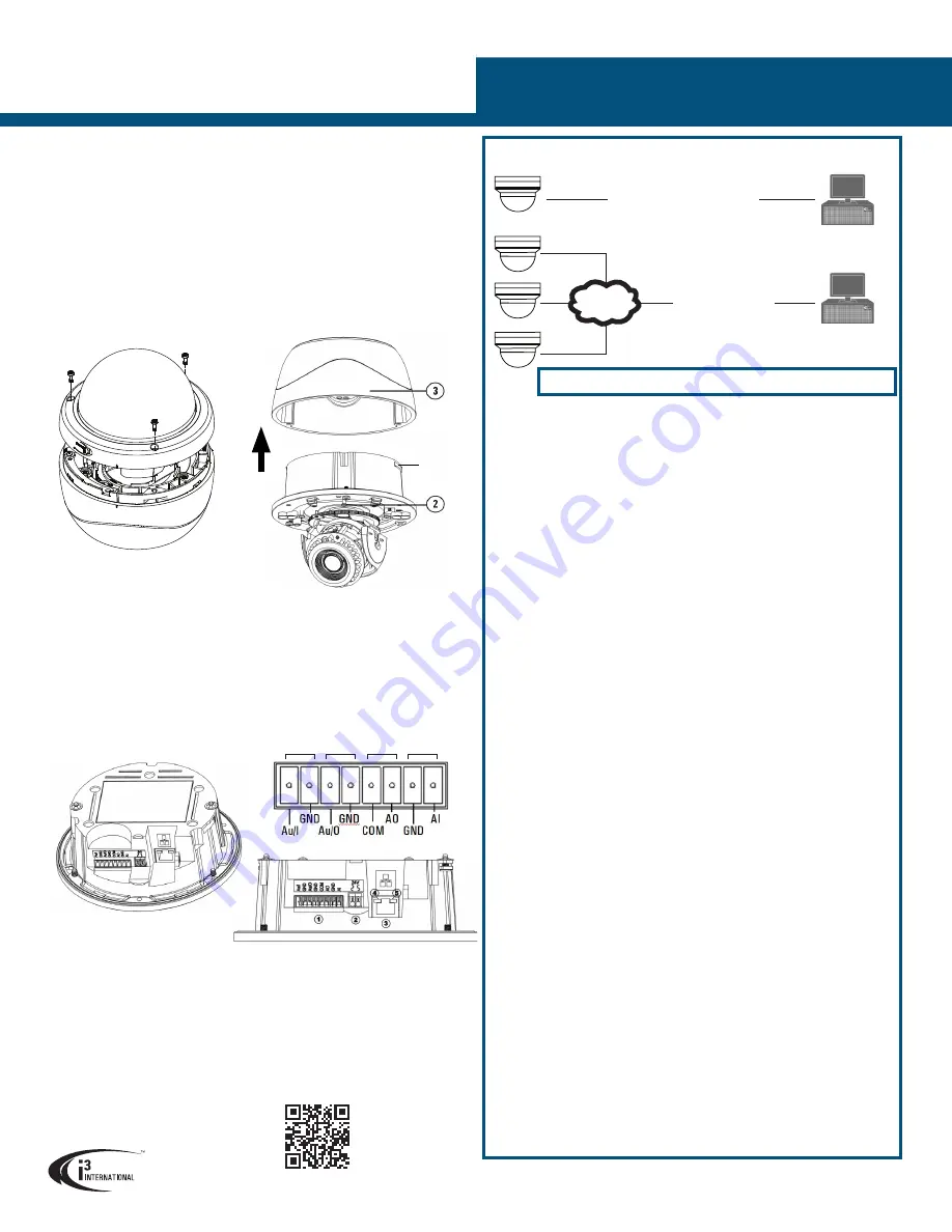
I/O CONNECTORS
Ax73RM-series 5MP IP Dome Camera
QUICK START GUIDE
i3 INTERNATIONAL INC.
1.866.840.0004
www.i3international.com
U.S.A 1967 Wehrle Drive, Suite 1,
PMB# 034 Buffalo NY, 14221
Canada 780 Birchmount Road, Unit 16,
Scarborough, ON, M1K 5H4
1. Camera’s back box
2. Screws attaching camera module to the back box
(x3, silver)
3. Camera module / second housing
4. Tilt bracket with locking screws
5. Inner liner / Shroud
6. IR board
7. Dome bubble housing / Dome cover
8. Screws securing the dome bubble housing to camera module (x3, silver)
9. Lexan bubble
10. 3/4” Top conduit hole. During installation, sealant must be used to maintain the IP66
status.
11. 3/4” Side conduit hole. During installation, sealant must be used to maintain the
IP66 status.
DISASSEMBLING THE CAMERA
CONNECT CAMERA TO i3 SRX-PRO SERVER
Camera’s default IP:
192.0.0.16
. Default Login / PW:
i3admin
/
i3admin
Connection Type 1:
i3 SRX-Pro Server
Crossover direct connection
LAN
i3 SRX-Pro Server
Via Gigabit Switch
Connection Type 2:
Audio In
Audio Out Alarm Out Alarm In
Locking
arms (x2)
1. Use the provided security Torx
key to loosen three screws se-
curing the dome bubble housing
to camera module (#8). Do not
completely remove the screws
from the dome bubble
2. Next, loosen three silver screws attach-
ing camera to the back box.
3. Remove camera’s back box and set
aside.
Once the camera dome bubble has been removed, Ax73RM input/output connectors will
be revealed on the camera’s module, including the microSD slot, Factory Reset and Factory
Default, analog RCA video jack, RJ-45 Ethernet/PoE connector, Audio and Alarm connectors
as well as a AC24V port.
1.
Audio and Alarm I/O connectors.
2.
AC 24V Port. Connect AC 24V power supply.
3.
RJ-45 Ethernet Connector / PoE. Connect RJ-45 network cable for ethernet/internet
connectivity. PoE (Power over Ethernet) is supported.
NOTE on Power:
Do not apply power until the camera is properly and securely mounted.
4.
Orange LED. Flashing orange LED indicates data transmission b/w camera and the
Internet.
5.
Green LED. Solid green LED indicates a current live connection.
1.
Close SRX-Pro Server software by pressing
Alt+Shift+Ctrl+F4
.
2.
Write down the IP address on the onboard NIC (LAN) (or on NIC1 if your SRX-Pro
Server has two onboard NIC cards).
3.
Connect your camera to i3 SRX-Pro Server (see diagram above).
4.
Turn on your Annexxus camera.
5.
It may be necessary to download and install AnnexxusConfigTool (ACT) from our
website (www.i3international.com). Follow the ACT installation instructions until
the application has been successfully installed on your SRX-Pro Server. For SRX-
Pro v3.3.3.69 and above ACT is already installed.
6.
Either double-click i3 Annexxus Configuration Tool icon on the desktop to launch
the ACT application or click the “ACT Config Tool” button on the IP Camera Tab
in SRX-Pro.
7.
ANNEXXUS Configuration Tool window will display a list of active network
cameras.
8.
Select the desired Annexxus camera in the list (left-click).
9.
In the
Device(s) Communication
area, enter the new IP Range (address) and
Subnet Mask of the camera. The new camera IP address must match the IP
range of your SRX-Pro LAN or NIC1 card (see Step 2).
E.g. If your SRX-Pro Server’s IP address is 192.138.10.122, change your
Annexxus camera’s IP address to 192.138.10.XXX.
Remember: Annexxus Cameras cannot share an IP address, each camera
requires its own unique IP address.
10.
Make sure the
Default Account
checkbox is checked off.
11.
Click
Update
. Wait a few moments for a successful confirmation message.
12.
Repeat Steps 9-12 for all detected Annexxus cameras in the ACT application
OR Select multiple cameras (Ctrl + left click) and enter IP range to assign IP
addresses sequentially to the selected cameras.
13.
Once the IP address of the Annexxus camera(s) has been changed, make sure
you can connect to the camera(s) through Internet Explorer:
a.
Launch Internet Explorer and enter the IP Address you have just assigned to
your Annexxus camera. The password window should be displayed.
b.
Enter the default camera User Name:
i3admin
and default Password:
i3admin
c.
Annexxus camera interface will be displayed in the Internet Explorer
window. You should be able to see the camera image on the screen.
If you do not see the camera image on the screen, call i3 International tech
support for troubleshooting tips: 1.877.877.7241
14.
Make sure that the latest version of GiPi updater is installed on your SRX-Pro
Server. You can download the updates from ftp://files.123ip.com/drivers/gipi.
Please contact i3 Technical Support team for access information.
15.
Once the latest GiPi updater has been installed, restart i3 SRX-Pro Server.
16.
Log In and go to the
Setup
->
IP Camera
tab.
17.
Click the
Search
button to display connected Annexxus cameras.
18.
Select the detected camera in the list and click
Select
.
19.
In the
Select IP Camera window, enter the default camera User Name:
i3admin
and default Password:
i3admin
, then click
Add
.
20.
The selected camera will be added to the IP Camera list.
21.
Assign the IP camera to the SRX-Pro video channel in the
Ch. In.
column.
22.
Select
i3 GiPi
from the
PTZ
column to enable motorized lens’ autofocus feature.
23.
Your Annexxus camera is now connected to SRX-Pro Server and is ready to
record. You may change resolution and frame rate for the Annexxus camera in
the IP Camera tab menu or you may choose to configure the camera’s advanced
settings.
QR Code to Complete
User Manual


