USER MANUAL
Page -3-
Am42R Analog Dome Camera
MENU
VIDEO
STANDARD
MAIN MENU
LANGUAGE
SAVE & EXIT
CONTRAST
DETECTION
COLOR
AUTO
BRIGHTNESS
SHARPNESS
MASKING
B/W
MANUAL
AE MODE
COLOR GAIN
ZOOM IN
SMART
AGC
3D NR
SENSE UP
MIRROR
AE
RESET
VIDEO
SETTINGS
FUNCTION
DAY &
NIGHT
WB
CAMERA MENU > MAIN MENU > AE
Under AE (Automatic Exposure) sub-menu, configure video image BRIGHTNESS, AE MODE,
AGC, and SENSE UP.
BRIGHTNESS:
Set the video image brightness value from 1 to
10, where 10 represents the highest brightness setting.
AE MODE:
Set the Automatic Exposure to GLOBAL AE or DWDR
(Digital WDR)
AGC:
Set the Automatic Gain Control to HIGH, MIDDLE or LOW.
Set to OFF to disable AGC function.
SENSE UP:
Sense Up function allows the user to select a slower shutter speed in order to
let extra light into a camera. This provides higher sensitivity in low light conditions. Set the
Sense Up value from 0 to 16.
AE
1. BRIGHTNESS ----|-8
2. AE MODE
DWDR
3. AGC
OFF
4. SENSE UP
--|--10
5. RETURN
CAMERA MENU > MAIN MENU > WB
Under WB (White Balance) sub-menu, set WB setting to either
AUTO or MANUAL mode.
AUTO:
Set to Auto to adjust White Balance automatically
MANUAL:
Set to MANUAL to configure R GAIN / B GAIN values.
Set between 1 and 10.
WB
1. R GAIN
--|--5
2. B GAIN
--|--5
3. RETURN
CAMERA MENU > MAIN MENU > DAY & NIGHT
Under DAY & NIGHT sub-menu, set the camera to either COLOR, B/W or SMART (auto) DAY
& NIGHT mode.
COLOR:
Set the camera to COLOR mode to keep the camera permanently in the daytime
(colour image) mode.
B/W:
Set the camera to B/W mode to keep the camera permanently in the nighttime
(black-and-white video image) mode.
SMART:
Set the camera to SMART mode to enable/disable
the camera’s IR LEDs (INFRARED LAMP). Set the SMART IR
level value between 1 to 5.
SMART
1. INFRARED-LAMP
OFF
2. SMART-IR
--|--2
3. RETURN
CAMERA MENU > MAIN MENU > VIDEO SETTING
Under VIDEO SETTINGS sub-menu, set the camera’s video image settings, including
CONTRAST, SHARPNESS, COLOR GAIN, 3D NR and MIRROR.
CONTRAST:
Set the CONTRAST value from 1 to 10, which 10 being the highest
contrast.
SHARPNESS:
Set the sharpness for EDGE and DETAIL value from 1 to 10.
COLOR GAIN:
Set the COLOR GAIN value from 1 to 10.
3DNR:
3D Noise Reduction function removes image noise from static and moving video
images. Set 3D NR value to HIGH, MIDDLE or LOW. Set to
OFF to disable 3D NR function.
MIRROR:
Mirror function flips the video image on the
screen. Set the MIRROR value to OFF, H, V or HV.
> Off: Do not use this feature
> H: flip images horizontally, left to right.
> V: flip images vertically, upside-down.
> HV: flip both horizontally and vertically.
CAMERA MENU > MAIN MENU > FUNCTION
Under FUNCTION sub-menu, set DETECTION, MASKING, and ZOOM IN functions.
DETECTION:
Set the motion sensitivity to WEAK, LOW, MIDDLE or HIGH. Next, configure
the Detection AREA.
AREA:
Configure settings for up to 4 separate Detection Areas. Set the status to OFF/
ON to disable/enable. Set the area border colour to WHITE, YELLOW, CYAN, GREEN,
MAGENTA, RED, BLUE, or BLACK. Use the joystick (Up/Down/Left/Right) to set the area’s
horizontal and vertical size and position.
Set the HORIZON SIZE / MOVE value in increments of 10 - from 0 to 720 (if using CVBS)
or 0 to 1280 (if using HD-TVI).
Set the VERTICAL SIZE / MOVE value in increments of 10 - from 0 to 480 (if using CVBS)
or 0 to 720 (if using HD-TVI).
DETECTION
1. SENSITIVITY
HIGH
2. AREA NO.0
3. AREA NO.1
4. AREA NO.2
5. AREA NO.3
6. RETURN
AREA
1. STATUS
HIGH
2. COLOR
WHITE
3. HORIZON SIZE
0
4. VERTICAL SIZE
0
5. HORIZON MOVE 0
6. VERTICAL MOVE 0
7. RETURN
MASKING:
Set up to 7 separate privacy (masking) area to block off areas of the
camera’s field of view. Set the background colour to WHITE, YELLOW, CYAN, GREEN,
MAGENTA, RED, BLUE, BLACK or MOSAIC.
Note:
Mosaic colour blurs video image.
Use the joystick (Up/Down/Left/Right) to set the area’s horizontal and vertical size and
position.
Set the HORIZON SIZE / MOVE value in increments of 10 - from 0 to 720 (if using CVBS)
or 0 to 1280 (if using HD-TVI).
Set the VERTICAL SIZE / MOVE value in increments of 10 - from 0 to 480 (if using CVBS)
or 0 to 720 (if using HD-TVI).
IMPORTANT: Video hidden behind the set Masking Area will be permanently lost.
ZOOM IN:
Set the ZOOM IN value from 50 to 100 in increments of 10.
100 setting displays complete image and 50 setting shows a zoomed-in image.
CAMERA MENU > MAIN MENU > RESET
Reset all the settings to the default.
MASKING
1. COLOR
WHITE
2. AREA NO.0
3. AREA NO.1
4. AREA NO.2
5. AREA NO.3
6. AREA NO.4
7. AREA NO.5
8. AREA NO.6
9. AREA NO.7
10. RETURN
AREA
1. STATUS
OFF
2. HORIZON SIZE
0
3. VERTICAL SIZE
0
4. HORIZON MOVE 0
5. VERTICAL MOVE 0
6. RETURN
CAMERA MENU > MAIN MENU > SAVE & EXIT
Select SAVE to save the adjusted settings and exit the OSD menu.
Select EXIT to discard all changes and exit the OSD menu.
VIDEO SETTING
1. CONTRAST
--|--5
2. SHARPNESS
3. COLOR GAIN
--|--10
4. 3DNR
HIGH
5. MIRROR
HV
6. RETURN
Joystick
UP
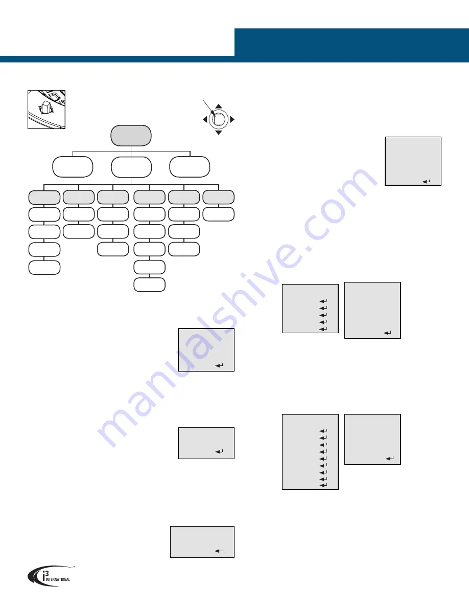
CAMERA MENU
Use the camera’s on-board joystick to adjust
camera settings.
Use the button in the middle of the Joystick
to access the camera OSD MENU and confirm
selection. Move the Joystick in UP/DOWN/LEFT/
RIGHT directions to navigate within camera
menus.
UP
Press to access
camera menu
and to confirm
selection.


