background image

Jan 05       


                                     P.19


E. 

OSD Switch 


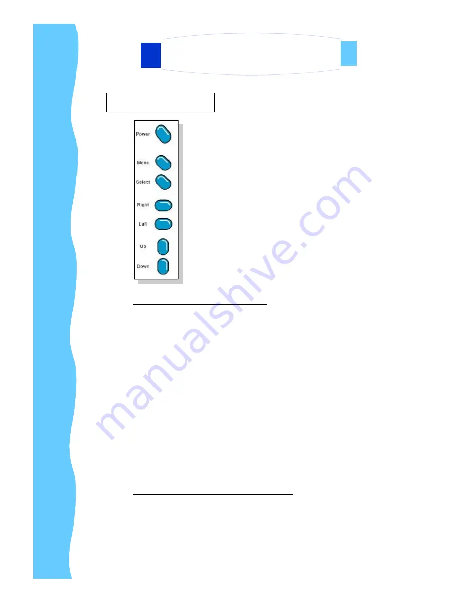
OSD Buttons (From Top to Bottom) 

 
         Power Switch:  

This button is used to power ON/OFF the LCD


Menu: 

This button is used to enter OSD main Menu 


 Select:  

This  button  is  used  to  select  for  composite  video 
input,  RGB  for  VGA  input  ,  S-Video  for  S-Video, 
Scart  for  Scart  signal  input,  DVI-D  for  DVI  digital 
signal input and TV( Optional) input. 

 
Right (

à

): 

This button is used to adjust the manual to Right


Left (

ß

):  

This button is used to adjust the manual to Left 


Up (

é

):                     This button is used to adjust the manual Upward  


Down(

ê

):                   This button  is used to adjust the manual Downward 


Steps to enter the OSD for function select: 


Push the 

Menu

 button to show the OSD on the screen. 

Push 

â

 & 

á

 to select the suitable category 

Push 

 Menu

 button twice to enter the category. 

Push 

â

,

á

,

é

 & 

ä

 to select the suitable function 


Push  

 Select

 button to confirm the function and exit the OSD


4. Using the System


AP-26 WT/ DP-26WT/ OP-26WT Series   


                                                                            User Manual


Содержание UltraView iAP26W

Страница 1: ...User Manual Innovative LCD Display Solutions AP 26W AP 26WT DP 26W DP 26WT OP 26W OP 26WT UltraView...

Страница 2: ......

Страница 3: ...Precautions Page 8 9 4 Using the System A Product Views Page 10 12 B I O Outlet Page 13 C Installation Procedures Page 14 D Setup Touchscreen Optional Page 15 i For Windows Page 15 ii For DOS Page 16...

Страница 4: ...olor active matrix thin film transistor TFT liquid crystal display to provide superior display performance A maximum resolution of 1 366 x 768 is ideal for displaying complex graphics and high definit...

Страница 5: ...ms 2 Introduction Disclaimer This information is subject to change without notice The producer of this manual accepts no responsibility for damage or claims resulting from misuse or misinterpretation...

Страница 6: ...ms 2 Introduction Disclaimer This information is subject to change without notice The producer of this manual accepts no responsibility for damage or claims resulting from misuse or misinterpretation...

Страница 7: ...ms 2 Introduction Disclaimer This information is subject to change without notice The producer of this manual accepts no responsibility for damage or claims resulting from misuse or misinterpretation...

Страница 8: ...le x 1 RCA Video Composite Video female x 1 RCA Audio Composite Audio female x 2 in out S video S video female x 1 Component Video Component Y Pb Pr x 1 VGA HDD D sub 15 Pin female x 1 DVI D DVI D x 1...

Страница 9: ...e user that any unauthorized changes or modifications to the unit if not expressly approved by the party responsible for compliance could void the user s authority of operating the equipment 1 Gently...

Страница 10: ...een The LCD is very delicate D Precautions Power 1 Use the type of power indicated on the marking label Plugs 1 Do not remove any of the prongs of the monitor s three pronged power plug 2 Disconnect t...

Страница 11: ...s Ensure that the total of all units plugged into the wall outlet does not exceed 10 amperes 5 Ensure that the total ampere ratings on all units plugged into the extension cord is not above the cord s...

Страница 12: ...A Product Views AP Series Front View AP Series Rear View Jan 05 P 10 4 Using the System AP 26 WT DP 26WT OP 26WT Series User Manual...

Страница 13: ...A Product Views Cont DP Series Front View DP Series Rear View Jan 05 P 11 4 Using the System AP 26 WT DP 26WT OP 26WT Series User Manual...

Страница 14: ...A Product Views Cont OP Series Front View OP Series Rear View Jan 05 P 12 4 Using the System AP 26 WT DP 26WT OP 26WT Series User Manual...

Страница 15: ...ect to the S video connector 6 Audio OUT Connect to the RCA audio connectors 7 Component Video IN Connect to Component Video connectors 8 VGA IN Connect to the 15pin sub D connector 9 DVI D IN Connect...

Страница 16: ...wer is turned off 2 Plug the signal cable to the signal connector at the rear of PC and the rear of the LCD monitor 3 Plug the power cord to the rear view of the LCD and switch on 4 Connect the power...

Страница 17: ...stalls the required TouchWareTM software files create a TouchWareTM software program files and place a TouchWareTM software icon on the Windows desktop and control panel TouchWareTM will also determin...

Страница 18: ...for DOS Pen Configuration utility for DOS Microcal Diagnostic utility ThruGlass control panel for DOS DOS help files If you do not plan to use any of the touchscreen files for windows you may want to...

Страница 19: ...diskette to the specified destination drive and directory Next the Install program automatically searched through the system and configures the touchscreen to the proper COM port interrupt and commun...

Страница 20: ...rt up your computer To manually load the DOS touchscreen driver 1 Close all applications and exit from Windows 2 Access the DOS command line prompt 3 Use the Change Directory cd command to switch to t...

Страница 21: ...ght This button is used to adjust the manual to Right Left This button is used to adjust the manual to Left Up This button is used to adjust the manual Upward Down This button is used to adjust the ma...

Страница 22: ...Bass Treble Balance Volume and Mute sub menu Picture In Picture Optional To enter into the PIP Size and PIP Position sub menu Channel Settings Optional To enter into the System Auto Store Manual Store...

Страница 23: ...e saturation level of the input signal Use the Left Right button to adjust Saturation from 0 100 Hue To adjust the Hue level of the input signal Use the Left Right button to adjust Hue from 19 0 19 Fl...

Страница 24: ...ft Right button to adjust Clock from 0 100 Phase To adjust input video sampling clock s phase Use the Left Right button to adjust phase from 0 255 Position To adjust the horizontal and vertical positi...

Страница 25: ...the Left Right button to adjust Treble from 0 15 Balance To perform balance adjustment of the output signal Use the Left Right button to adjust Balance from 10 0 10 Volume To adjust the volume level o...

Страница 26: ...picture size selection of the input signal Use the Up Down button to select the PIP sizes from Off Small Medium Large PAP POP PIP Position To perform PIP small picture position of the input signal Us...

Страница 27: ...e Left Right button to select Yes No for Auto Store Manual Store To perform Manual Store function for TV Channel setting Use the Left Right button to moving the Channel Setting pointer on the Signal I...

Страница 28: ...select OSD Language from 1 English 2 Chinese 3 Deursch 4 Francais 5 Espanol 6 Italiano OSD Position To perform OSD position of the screen Use the Left Right Up Down button to select the OSD po sition...

Страница 29: ...nction show in the screen Show the information about Source Resolution Hsync Vsync Factory Reset To perform reactivate to the factory reset function Use the Left Right button to select Yes No for Fact...

Страница 30: ...ft adjusts menu settings 5 Menu Setting Buttons switch menu hot keys 6 Mute Switch the sound on or off 7 Channel switch the TV channel 8 Menu select a menu 4 Using the System Disclaimer This informati...

Страница 31: ......

Страница 32: ......

Отзывы: