background image


QPC-DC Series USER MANUAL 

4-24


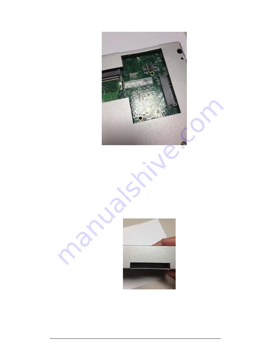
3)  Swap/Install the Half Slim SSD. 

4)  Reverse the steps from section 4.2 to re-attach the main system box to the 

system. 


4.6      Install 3GS Sim Card (Optional) 


1)  Follow section 4.2 to detach the main system box from the system. 

2)  Flip the main system box to the top side to gain access to the 3GS SIM card 

slot. (Like shown in the following picture) 


3)  Insert the SIM card and reverse the steps from section 4.2 to re-attach the main 

system box to the system. 


Содержание QPC-DC 1500

Страница 1: ...QPC DC Series User Manual i Tech Company LLC TOLL FREE 888 483 2418 EMAIL info itechlcd com WEB www iTechLCD com...

Страница 2: ...s a digital device pursuant to part 15 of the FCC rules These limits are designed to provide reasonable protection against harmful interference when the equipment is operated in a commercial environme...

Страница 3: ...ual is sold or licensed as is Should the programs prove defective following their purchase the buyer assumes the entire cost of all necessary servicing repair and any incidental or consequential damag...

Страница 4: ...x 1 User guide CD driver x 1 Wall Mount Bracket 2pc x 1 In Wall Front Mount Locking Beads x 1 Make sure that all of the items listed above are present If any of the above items is missing contact your...

Страница 5: ...operating system must be loaded first before installing any software into the equipment 9 Disconnect the power cord from the computer before any installation of internal components Make sure both the...

Страница 6: ...2 13 2 3 Installation Memory Module 2 13 CHAPTER 3 TOUCH SCREEN 3 15 3 1 Introduction 3 15 3 2 Specifications 3 15 3 3 Touch Screen Software Driver 3 15 3 4 Touch Screen Care and Clean 3 16 3 5 Troubl...

Страница 7: ...ctor 4 25 4 8 COM2 RS232 RS422 RS485 9 pin D SUB Connector 4 25 4 8 1 COM3 RS232 Serial Port Connector 9 pin D SUB Connector 4 26 4 9 USB1 USB 2 0 3 0 Port 1 2 USB Type A Connector 4 26 4 10 LAN1 Giga...

Страница 8: ...solution and minimizes power consumption to as little as 24 watts when running at the speed of Dual Core 1 8GHz bringing up a quieter and cooler system The versatile QPC DC SERIES can support one 2 5...

Страница 9: ...isplay mirroring multiple mode Network 2x Realtek RTL8111C 10 100 1000 Base T fast Ethernet 802 11g Wireless LAN module Optional Built in 3GS Module Optional Audio AC97 Codec Line in Line out Mic 2W A...

Страница 10: ...32GB 64GB Half Slim SSD Optional I O PORTS USB QPC DC A 0840 1040 1210 1500 1850 B 0840 1040 4 x USB 2x USB 3 0 2x USB 2 0 ports QPC DC B 1500 8 x USB 2 0 ports 2x USB 3 0 6X USB 2 0 ports QPC DC B 1...

Страница 11: ...4 x 45 4 L x W x H mm QPC DC 1040 218 5 x 284 x 45 4 L x W x H mm QPC DC 1210 264 x 330 x 48 L x W x H mm QPC DC 1500 307 x 390 x 51 L x W x H mm QPC DC 1850 307 x 495 x 55 L x W x H mm Weight QPC DC...

Страница 12: ...QPC DC Series USER MANUAL 2 11 Chapter 2 USING THE SYSTEM 2 1 Identifying the System 2 1 1 Back Top view QPC DC 1500 2 1 2 Back Bottom view QPC DC 1500 A...

Страница 13: ...ort 3 Connect the male end of the power cord to an electrical outlet 4 Connect the USB CD ROM drive 5 Connect the female end of the power adapter cord to the AC inlet located at the rear side of the Q...

Страница 14: ...into the system 1 Use the External USB CD ROM DVD ROM Drive to load an OS from a bootable CD Recent releases of operating systems include setup programs that load automatically and guide you through...

Страница 15: ...s USER MANUAL 2 14 Available DDR3 configurations refer to the table below for available DDR3 configurations on the mainboard Slot Module Size Total SODIMM1 1GB 2GB 4GB 1GB 4GB Maximum supported system...

Страница 16: ...controller and a software driver 3 2 Specifications QPC DC Series supports HIGGSTEC touch panel Please check specifications as following Input Method Finger gloved hand or touch stylus Optical Transm...

Страница 17: ...hardware transmits touch coordinates correctly then the problem is probably with the driver or application software Hardware problems may be caused by the touch screen controller cabling power supply...

Страница 18: ...gnostics that are displayed when the touch panel utility driver software is loaded to check for specific faults Also check whether the controller is transmitting any touch data No touch data When no t...

Страница 19: ...serial mouse or other serial devices directly to the connector y VGA Port The DB15 pin female connector is connecting to LCD panel y USB Ports USB ports are for attaching USB devices such as keyboard...

Страница 20: ...e System to the back and have the system box face towards you 2 Remove L and R screw in the side of the system box like shown in the following picture 3 Once the locking screws are removed pull the ma...

Страница 21: ...tures 5 To replace and reinstall the Main system box please reverse the above steps 4 3 Install Upgrade Memory 1 Follow the steps from section 4 2 to remove the main system box 2 Once removed flip the...

Страница 22: ...g clips snap back in place and the SODIMM is properly seated 6 Reverse the steps from section 4 2 to re attach the main system box to the system 4 4 Install Swap HDD 1 Follow the steps from section 4...

Страница 23: ...ANUAL 4 22 4 Slightly Loosen the HDD top locking screw completely like shown in the following picture 5 Push outward on the top locking screw that was loosened in step 4 to remove HDD Like shown in th...

Страница 24: ...attach the main system box back to the system 4 5 Install Half Slim SSD For D2550 only 1 Follow section 4 2 to detach the main system box from the system 2 Flip the main system box to the back side t...

Страница 25: ...he system 4 6 Install 3GS Sim Card Optional 1 Follow section 4 2 to detach the main system box from the system 2 Flip the main system box to the top side to gain access to the 3GS SIM card slot Like s...

Страница 26: ...Standard 9 pin D SUB Connector 1 5 6 9 RS232 Mode Select by CMOS setup Signal Name Pin Pin Signal Name DCD 1 2 RXD TXD 3 4 DTR GND 5 6 DSR RTS 7 8 CTS RI Funtion Select by JP1 9 10 N C RS422 Mode Sel...

Страница 27: ...5 6 NC NC 7 8 NC 12V 5V Function Select by JP1 9 4 8 1 COM3 RS232 Serial Port Connector Standard 9 pin D SUB Connector 1 5 6 9 RS 232 Mode Select by CMOS Setup Signal Name Pin Pin Signal Name DCD 1 2...

Страница 28: ...Connector Standard RD 45 with LED LED Signal Name Yellow Link Active Green 10 100M LAN Speed Orange Giga LAN Speed 4 10 1 LAN2 Giga bit Ethernet Connector Standard RD 45 with LED LED Signal Name Yello...

Отзывы: