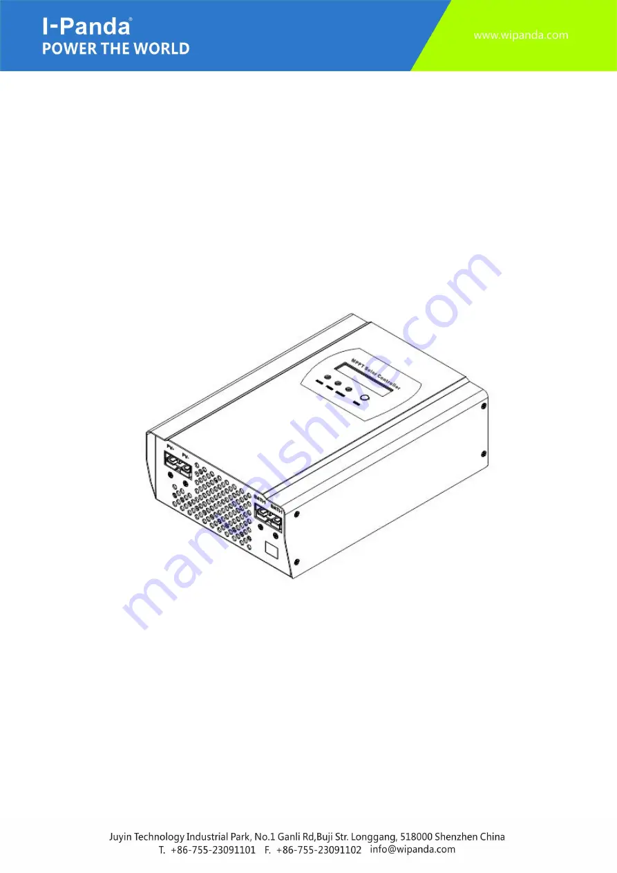
MPPT Solar Charge Controller
12V/24V/48V Automatic Recognition
40A 50A 60A Series
Manual
Страница 1: ...MPPT Solar Charge Controller 12V 24V 48V Automatic Recognition 40A 50A 60A Series Manual...
Страница 2: ...ns 4 3 Unpacking 6 4 Assembly 7 5 MPPT Controller Connection 8 6 Steps for Commissioning or Shutdown 11 7 LED LCD and Function Key 12 8 Technical Parameters 17 9 Maintenance and Cleaning 20 10 Storage...
Страница 3: ...hould be stored in the immediate vicinity of the charge controller and must be accessible at all times 1 4 Symbols Used The following types of safety messages and general information appear in this do...
Страница 4: ...The solar charge controller can become hot during operation Avoid contact during operation Never put any goods onto the controller Caution Unit may emit some radiation which may be harmful Do not sta...
Страница 5: ...lar charge controller Before using the solar charge controller please read all instructions and cautionary markings on the solar charge controller and all corresponding sections of this guide Contact...
Страница 6: ...packing 3 1 Parts List Object Quantity Description A 1 unit Charge controller B 2 pcs 4 pcs Hang bracket screws C 1pce CD D 2 pcs PV input blue DC output red E 1 pce RS232 to RJ45 comm cable F 1 pce M...
Страница 7: ...d be easy to remove from the mounting location at any time The ambient temperature should be between 4 and 140F 20 and 60 C to guarantee optimal operation Danger Possible fire and explosion hazard The...
Страница 8: ...are present and dangerous Disconnect the PV array using a disconnection unit and secure it against accidental reactivation Disconnect the circuit breaker and ensure that it cannot be reconnected Ensu...
Страница 9: ...troller It should be outdoor uv rated and we recommend 10Awg to prevent excessive losses due to distance It is beneficial to increase the dc voltage to optimize performance and decrease inefficiencies...
Страница 10: ...as RS232 connector check the following picture 5 3 1 RS232 Communication RS232 is one standard communication interface It transmits the data between PC and one charger controller One end of the cable...
Страница 11: ...onnection If the PV module voltage is in the charging range then the controller will start to work 6 2 Steps for Proper Shutdown Step 1 Open the PV breaker to disconnect panels from controller Step 2...
Страница 12: ...er Blue Standby Green Power on off off on Charge off on on Fault on off on Bat Chose Type off off off 7 1 1 Smart Charge Modes This controller has 3 modes Constant charging stage CC Mode Constant volt...
Страница 13: ...ode 1 mode website 2 BAT checking 3 PV volt checking 4 In volsen checking 5 Out volsen checking Remarks The controller would be in detection automatically Then it enter the normal mode or failure mode...
Страница 14: ...r Over current at output current Out Relay Fault Output relay interrupted Output Short Short circuit in the sensor cable BAT Polar Error Battery polar connect error BAT Volt Error Battery is not stand...
Страница 15: ...he function key once LCD will display one type of battery Step 3 After choosing the matched battery you need press the function key for 3 seconds to set types of battery 7 4 MPPT and PC Connection Ste...
Страница 16: ...16 Step2 Parameters setting Step 3 Battery type Step 4 Software can display battery type information and model name etc as below...
Страница 17: ...eypad on the display 8 Technical Parameters Model I P SMART1 DC12V 24V 48V se ries 40A 50A 60A Charge Mode Maximum Power Point Tracking Method 3 stages fast charge MPPT constant voltage floating charg...
Страница 18: ...4V 48V system Please check the charge voltage according to the battery type form Floating Charge Voltage 12V 24V 48V system Over Charge Protection Voltage 12V system 14 6V 24V system 29 2V 48V system...
Страница 19: ...gree Other Parameters Noise 40dB Thermal methods Forced air cooling fan speed rate regulated by temperature when inner temperature is too low fan runs slowly or stops when controller stops working fan...
Страница 20: ...en thermal fuses from the sockets A and B 3 Insert new thermal fuses included in the scope of delivery 4 Close the solar charge controller as described in section Closing the solar charge controller 5...
Страница 21: ...lation site at that time 11 Recovery Processing and Warranty 11 1 Recovery Processing When the controller mal functions please check the following questions and contact our customer service representa...
Страница 22: ...of repairs would be charged 11 3 Guarantee Card User name Country Address Telephone Number Pose Code Email Date of Purchase Vendor Date of Installation Installer Installer Contact Information Solar C...