background image

Installation 

User Manual


22 


4.4.1 

Installation Parts 

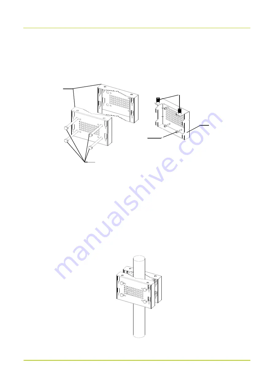
The following figure shows the parts needed for installation, including the auxiliary fixture, back panel, 

latches and M6 screws.   


4.4.2 

Installing the Product 

Installation on Pole 

You can install the product at its back or at its left side. The pole diameter should be between 60 mm to 114 

mm.  

Installing at Back 

1.  Mark the installation position of the auxiliary fixture on the pole by using a marking pen.   

2.  Place the auxiliary fixture onto the pole, insert four bolts into the auxiliary fixture and then tighten four 

nuts by using a torque wrench.   


3.  Secure the back panel onto the back of the product using four M6 screws.   

Auxiliary


Fixture

Captive


Screw

Back


Panel

M6


Screw

Bolt

Содержание DS-9300

Страница 1: ...User Manual...

Страница 2: ...he purchaser regarding the Company s computer programs Any of the Company s computer programs may not be copied modified distributed decompiled or reverse engineered in any manner without the prior wr...

Страница 3: ...to try to correct the interference by one or more of the following measures Reorient or relocate the receiving antenna Increase the separation between the equipment and receiver Connect the equipment...

Страница 4: ...C Radiation Exposure Statement This device must be restricted to work relate exposure Environment This equipment should be installed and operated with minimum di antenna your body ISEDC exposition aux...

Страница 5: ...11 3 2 Donor Unit Interfaces 12 3 2 1 Cable access Donor Unit 12 3 2 2 Wireless access Donor Unit 13 3 3 Remote Unit Interfaces 13 3 4 Interface Description 14 3 5 Interface Definition 15 3 6 LED Ind...

Страница 6: ...bugging 37 6 1 Preparation 37 6 2 Procedure 37 6 2 1 Querying Parameters 39 6 2 2 Setting Parameters 39 6 2 3 Upgrade 41 6 2 4 Exporting the Logs 42 7 System Maintenance 43 7 1 Care and Cleaning 43 7...

Страница 7: ...tes references that can further describe the related topics Caution Indicates situations that could cause data loss or equipment damage Warning Indicates situations that could cause minor personal inj...

Страница 8: ...r Guide Courier New Denotes commands and their execution results To set the IP address run the following command vos cmd m name IP Revision History Document Version Product Version Release Date Descri...

Страница 9: ...nitoring DS 9300 provides remote monitoring through IP network and local monitoring through RS232 serial port Users can manage all devices through the network management system or remotely query confi...

Страница 10: ...from the BS The remote unit is installed away from the donor unit over a fiber link The following figure shows the networking of DS 9300 and the BS Various topologies are available for networking betw...

Страница 11: ...ation For low configuration of chain topology only one of the SFP ports on the donor unit is used and it can connect to at most four remote units N 4 Donor Unit Remote Unit 1 Remote Unit N Remote Unit...

Страница 12: ...ow Configuration For low configuration of hybrid topology each SFP port of the donor unit can connect up to four remote units while one donor unit can connect to at most four remote units High Configu...

Страница 13: ...Gain Adjustment Error 1 dB gain of 0 20 dB 1 5 dB gain of 21 30 dB 8 Noise Figure Wireless access 5 dB 5 dB 9 Max Input Level Cable access 10 dBm Wireless access 10 dBm 10 dBm 10 Automatic Level Cont...

Страница 14: ...dBc 500 kHz 18 Optical Bypass optional When the remote unit is powered down or the optical path is faulty the optical path is automatically bypassed and other cascaded remote units are not affected 19...

Страница 15: ...65 Remote Unit IP65 30 Safety IEC 60950 Compliance 31 EMC IEC 61000 class B Compliance 32 Dimensions Cable access Donor Unit 44 mm x 442 mm x 320 mm Wireless access Donor Unit 142 mm x 300 mm x 385 mm...

Страница 16: ...Power Cord 1 Crown Screw 4 Documentation Kit 1 2 2 Wireless access Donor Unit Item Qty Item Qty Main Unit 1 Signal Cable 8 core 1 Packing material 1 Power Cord 1 Mechanical parts of Die Casting Machin...

Страница 17: ...e unit its LED indicators and connectors are provided on the front and rear panels of the rack The following figure shows the appearance of the remote unit For the donor unit its LED indicators are pr...

Страница 18: ...Getting Started User Manual 12 3 2 Donor Unit Interfaces 3 2 1 Cable access Donor Unit 1 2 3 4 5 6 7 8 10 10 11 9...

Страница 19: ...User Manual Getting Started 13 3 2 2 Wireless access Donor Unit 13 14 15 6 1 7 8 9 11 3 12 3 3 Remote Unit Interfaces 1 12 13 11 16 6 7 8 9 14...

Страница 20: ...onnected to computer through the serial cable for debugging and monitoring 7 CPRI 0 3 Optical port SFP connector dual layer The donor unit connects to remote units through CPRI interface 8 IP Remote m...

Страница 21: ...al alarm 1 Closed Alarm Open No alarm 2 INT2 External alarm 2 Closed Alarm Open No alarm 3 INT3 External alarm 3 Closed Alarm Open No alarm 4 GND Ground signal Common terminal 5 OUT1 Reserved Customiz...

Страница 22: ...Green Glowing Remote communication works well Off Remote communication error PWR Green Glowing The device is properly powered Flashing or off The device is not properly powered RUN Green Flashing The...

Страница 23: ...User Manual Getting Started 17 LED Indicator Color Status Description Flashing or off Optical synchronization error...

Страница 24: ...f the power system during operation in moist environment The equipment should be well earthed to avoid damage as a result of lightning strikes Do turn off the power before assembly or disassembly Do v...

Страница 25: ...d is strictly prohibited The slant of the ladder is suggested to be 75 When using a ladder place it on a stable ground and take protective measures on the base part of the ladder for skid resistance H...

Страница 26: ...d at its back the space of at least 800 mm should be left in front of product for product installed at its left side the space of at least 800 mm should be left at its right side Install the product u...

Страница 27: ...ollowing table lists the required tools Regular Tools Torx screwdriver Philips driver flat blade screwdriver adjustable wrench Allen wrench cross type torque screwdriver combination wrench rubber hamm...

Страница 28: ...ts back or at its left side The pole diameter should be between 60 mm to 114 mm Installing at Back 1 Mark the installation position of the auxiliary fixture on the pole by using a marking pen 2 Place...

Страница 29: ...the back panel of the product Installing at Left Side Installing the product at left side and installing the product at back are almost the same The only difference is that the back panel is secured...

Страница 30: ...he product Installing at Back 1 Place the auxiliary fixture on the wall at the installation position and then mark the anchor points by using a marking pen 2 Drill holes at the anchor points and then...

Страница 31: ...l Installation 25 4 Secure the back panel onto the back of the product using four M6 screws 5 Insert the back panel into the auxiliary fixture and tighten the captive fasteners on the back panel of th...

Страница 32: ...alling the product at left side and installing the product at back are almost the same The only difference is that the back panel is secured to the left side rather than back of the product The follow...

Страница 33: ...ble must be complete and cannot have splices or welding points Avoid knotting or twisting the cable Requirements for Laying Out Grounding Cables The grounding cable cannot be led in aerially but burie...

Страница 34: ...ccess Donor Unit Cable List Cable One end at DS 9300 device Other end Connector Connected to Connected to Grounding Cable Ring Terminal Ground Terminal Grounding Bar RF Antenna N M BS Interface Antenn...

Страница 35: ...ed to Connected to Power Cable Round Electric Connector AC Interfaces External Power Supply Optical Fiber SFP SFP CPRI 0 1 Interfaces Optical Fiber Network Monitoring Cable 8 pin 1 pin Aviation Connec...

Страница 36: ...ion User Manual 30 Wireless access Donor Unit Remote Unit Installing the Grounding Cable 1 According to the route make a grounding cable with proper length and install ring terminals at both ends of t...

Страница 37: ...and tighten the connector using the torque wrench 3 Connect the donor unit to the coupler and connect the other end of the RF antenna from the remote unit to the service antenna If the antenna is ins...

Страница 38: ...ties 8 Attach labels or tags to the installed cable Installing the Power Cable Note Power cable delivered with DS 9300 device is 3 18 AWG cable 1 Connect one end of the power cable to the PWR connect...

Страница 39: ...dopts a dual fiber single mode optical module with a transfer rate of 1 25 Gbps a wavelength of 1 310 nm and a communication distance of 20 km a Rotate the bail clasp latch down b Insert the optical m...

Страница 40: ...ice is securely installed 3 Waterproof caps are installed on idle connectors and securely fastened 4 All power cables or grounding cables are not short circuited or reversely connected and must be int...

Страница 41: ...User Manual Installation 35 If the RUN indicator flashes green and the ALM indicator is off the status of DS 9300 device is normal...

Страница 42: ...ower Off 5 1 Powering On Toggle the power switch on DS 9300 device to the ON position to power it on Wait a few minutes and check the status of LED indicators 5 2 Powering Off Toggle the power switch...

Страница 43: ...set to the same network segment 192 168 1 X X cannot be 100 The computer for running the PSS must meet requirements specified in the following table Item Description Operating system Windows7 or above...

Страница 44: ...will appear in the message pane 3 Select Ethernet tab set the Destination and Port and click Connect Note For debugging through the serial cable select the Serial tab set the Serial and Baudrate 1152...

Страница 45: ...arameter To query all parameters on the line click the blank tab above the checkbox as shown in the figure below 6 2 2 Setting Parameters 1 In the parameter list click the blank space under Setting ta...

Страница 46: ...responding donor antenna of the wireless access donor unit c Select the Device Information tab and modify the configuration according to the following table Parameter Value IP Address This parameter i...

Страница 47: ...d needs handling 2 Click Setting the result will be displayed in the message pane Note To restore the factory settings click Factory Reset 6 2 3 Upgrade PSS allows you to upgrade the main program of t...

Страница 48: ...e fails or you want to roll back to the former version perform the upgrade using the old upgrade file 6 2 4 Exporting the Logs PSS allows you to export the operation logs 1 In the Log area click Path...

Страница 49: ...the dust and fine particles on the product surface and charging piece with a clean and dry lint free cloth or a brush regularly Use a non woven cloth with neutral cleanser to clean the device after lo...

Страница 50: ...maximum temperature threshold to 90 C If the alarm still exists cool the device down Door Alarm Check whether the cabinet door is properly closed If the alarm still exists after the door is closed ch...

Страница 51: ...or troubleshoot the faulty module Or replace the faulty module if necessary The ALM indicator glows red solidly A module is faulty Replace the faulty module The ALM indicator flashes red A connector...

Страница 52: ...efault value is 192 168 1 100 Subnet Mask This parameter is subject to actual requirements The default value is 255 255 255 0 Default Gateway This parameter is subject to actual requirements The defau...

Страница 53: ...0 to 255 1 Hytera 2 Reserved Device Type The range is 1 to 13 1 DCCD 2 DCR 3 DICR 4 LA 5 DWCD 6 DCBD 7 DBR 8 DWBD 9 DCCD L 10 DWCD L 11 DCBD L 12 DWBD L 13 Reserved Device Number Enter up to 20 chara...

Страница 54: ...he range is 0 to 65535 This parameter is subject to actual requirements Port number of the RMS Monitor Center Site Description This parameter is subject to actual requirements Real time Sampling Param...

Страница 55: ...Donor Unit Connection Indicator 0 Not connected 1 Connected Whether a donor unit is connected Setting Parameters Parameter Configuration Remarks Downlink Input Over power Threshold dBm The range is 1...

Страница 56: ...tch 0 Enable 1 Disable Remote Unit Delay Auto compensation Switch 0 Enable 1 Disable Uplink Digital Attenuation dB The range is 0 to 20 Downlink Digital Attenuation dB The range is 0 to 20 Monitor Boa...

Страница 57: ...put Over power Alarm Enable 0 Disable 1 Enable Uplink Output Over power Alarm Enable 0 Disable 1 Enable Uplink Local Oscillator Unlock Alarm Enable 0 Disable 1 Enable Downlink Local Oscillator Unlock...

Страница 58: ...power Alarm 0 Normal 1 Fault Uplink Input Over power Alarm 0 Normal 1 Fault Downlink PA Over current Alarm 0 Normal 1 Fault Uplink Local Oscillator Unlock Alarm 0 Normal 1 Fault Downlink Local Oscill...

Отзывы: