600 SRM 496
Pistons and Connecting Rods Repair
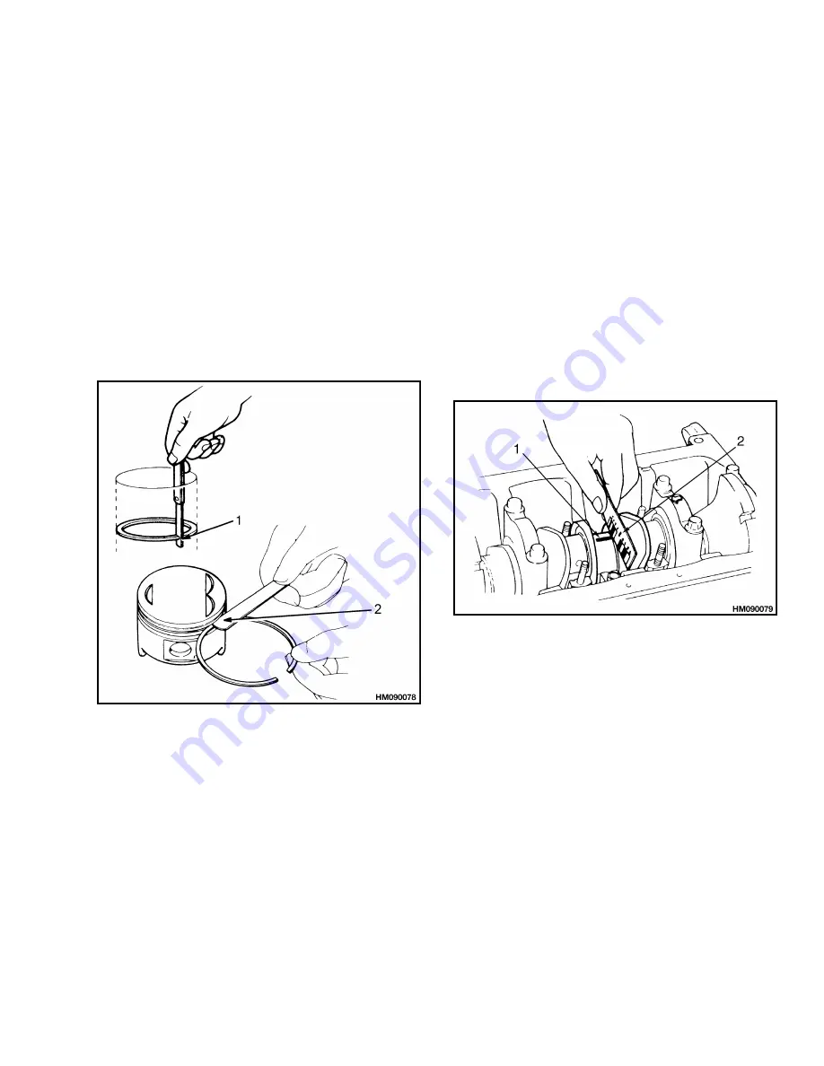
of end clearance of each piston ring. See Fig-
ure 31. Correct dimensions are as follows:
Top Piston Ring - 0.20 to 0.35 mm (0.008 to
0.014 in.)
2nd Piston Ring - 0.15 to 0.30 mm (0.006 to
0.012 in.)
Oil Ring - 0.30 to 0.90 mm (0.012 to 0.035 in.)
Maximum clearance is 1.0 mm (0.039 in.)
2.
Measure clearance between piston ring and
groove in piston. See Figure 31. Correct dimen-
sions are as follows:
Top Piston Ring - 0.03 to 0.07 mm (0.0012 to
0.0028 in.)
2nd Piston Ring - 0.03 to 0.07 mm (0.0012 to
0.0028 in.)
Maximum clearance is 0.15 mm (0.0059 in.)
1.
PISTON RING END CLEARANCE
2.
PISTON RING GROOVE CLEARANCE
Figure 31. Piston Rings Measurement
Connecting Rods and Bearings
1.
Use alignment tool to check connecting rods for
straightness. Maximum amount of distortion per
100 mm (4.0 in.) is 0.04 mm (0.0016 in.).
If amount of distortion is greater than specifica-
tion, install new rod or use press to straighten
connecting rod.
Clean rod bearings and crankshaft journals. To
check bearings for wear, measure clearance be-
tween rod bearings and journals. See Figure 32.
a. Put plastic gauge material on crankshaft
journals and install rod caps. Tighten cap-
screws for rod caps to 51 to 56 N•m (38 to
41 lbf ft). Do not rotate connecting rod.
b. Remove rod caps. Plastic gauge material will
adhere to journals or rod caps.
c.
Use graduations on scale to measure width
of plastic gauge material at its widest point.
Correct clearance is 0.027 to 0.067 mm
(0.0011 to 0.0026 in.).
If any clearance is
greater than specification, replace all rod
bearings.
1.
BEARING
2.
PLASTIC GAUGE
Figure 32. Connecting Rod Bearings Clearance
Check
ASSEMBLE AND INSTALL
1.
Align oil port on large end of connecting rod with
F mark on piston. See Figure 33. Lubricate pis-
ton pin and bore in piston with engine oil.
2.
Use press to install piston pin. Amount of force
required to push pin into piston must be 500 to
1500 kg (1102 to 3306 lb). If force is not correct,
replace piston pin and/or connecting rod.
Use special tool to make sure piston pin is in-
stalled to correct depth. After installation, check
that piston moves freely on piston pin.
13
Содержание D010
Страница 37: ......
Страница 38: ...TECHNICAL PUBLICATIONS 600 SRM 496 2 01 4 96 1 96 1 95 9 93 4 93 Printed in U S A ...


