background image

Repairs

2200 SRM 1357

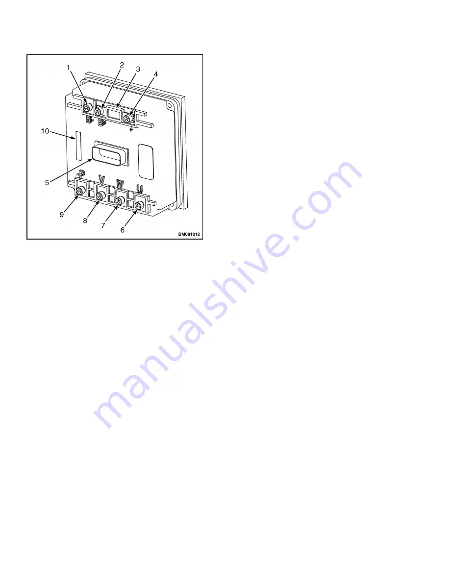
1.

B– TERMINAL

2.

B+ TERMINAL (POS CONNECTION STD)

3.

MAIN FUSE (STD LOCATION)

4.

+ TERMINAL (POS CONNECTION EE)

5.

MAIN CONNECTOR

6.

TRACTION MOTOR POS (TERMINAL U)

7.

TRACTION MOTOR POS (TERMINAL W)

8.

TRACTION MOTOR POS (TERMINAL V)

9.

PUMP MOTOR POS (TERMINAL P)

10. LABEL (PART NUMBER)

Figure 7. Controller Wiring

4.

Discharge the capacitor. See Special Precautions
in this section.

5.

Tag and disconnect wires from the controller. See
Figure 7.

6.

Remove mounting screws and remove controller.

Install

1.

Install replacement controller on lift truck using
mounting hardware.

2.

On models with the Arctic option, install shield
box to controller studs and secure using four
nuts.

3.

Connect wires and cables to the proper terminals
as identified during the removal procedure.

4.

Connect battery and turn the key switch to the
ON position.

5.

Turn parking brake to the OFF position and test
for proper operation.

6.

Install the drive unit compartment covers. See
the section Periodic Maintenance 8000 SRM
1368.

CONTROL MODULE

Check

The control module converts analog signals from the
control handle to digital signals for the controller to
read. If the controller is reporting an input error
fault code, then the control module may be malfunc-
tioning. Check the control module using the follow-
ing steps. See Figure 8.

1.

Connect the battery and turn the key switch to
the ON position. Make sure the parking brake
switch is in the OFF position.

2.

Connect the negative voltmeter lead to the nega-
tive battery cable connection at the controller.

3.

Disconnect the output connector (J5) from the
control module.

4.

Using the positive voltmeter lead, test pin #6 at
the output connector (J5-6).

5.

If there is no voltage at J5-6 then troubleshoot
the controller. See the section AC Motor Con-
troller 
2200 SRM 1352.

6.

If the voltmeter shows the proper reading (+24V),
check the input connector (J4) voltages. See Ta-
ble 2.

NOTE:

Voltage should be present at J4-2, J4-3, J4-6,

and J4-9 ONLY while activating the corresponding
function. See Table 2.

7.

If the input values differ from those in the table,
troubleshoot the control handle components, con-
troller, and wiring. Make any necessary repairs,
and recheck the input values.

8.

If the input values are correct, replace the control
module. See Remove.

NOTE:

ETACC may be used to check communication

between control handle, control module, and traction
controller. See the section AC Motor Controller
2200 SRM 1352.

10

Содержание B476

Страница 1: ...Hyster B476 T5ZAC Forklift Service Repair Manual...

Страница 2: ...ELECTRICAL SYSTEM T5ZAC B476 T7ZAC B477 C60ZAC B478 C80ZAC B479 PART NO 1687930 2200 SRM 1357...

Страница 3: ...Replacement parts must meet or exceed the specifications of the original equipment manufacturer Make sure all nuts bolts snap rings and other fastening devices are removed before using force to remov...

Страница 4: ...e 13 Install 14 Parking Brake Switch 15 Remove 15 Install 15 Fuses 15 Horn 16 Replace 16 High Speed Switch Assembly 16 Remove 16 Install 16 Control Handle 17 Disassemble 17 Hand brake 18 Upper Cover 1...

Страница 5: ...ore information Please click here Then get the complete manual NOTE If there is no response to click on the link above please download the PDF document first and then click on it Have any questions pl...

Страница 6: ...Table of Contents Electrical System TABLE OF CONTENTS Continued General Troubleshooting 26 This section is for the following models T5ZAC B476 T7ZAC B477 C60ZAC B478 C80ZAC B479 ii...

Страница 7: ...information on troubleshooting fault codes adjusting parameters and testing the motor controller See the section AC Motor Repair 620 SRM 1283 for general information on traction motor troubleshoot in...

Страница 8: ...General 2200 SRM 1357 A RH SIDE B LH SIDE C FORWARD D REVERSE Figure 1 Truck Orientation 2...

Страница 9: ...the brake coil energizes disengaging the brake This pulls the brake pressure plate away from the friction disc allowing the drive motor to turn freely A two stage hand brake assembly see Figure 2 is m...

Страница 10: ...BATTERY DISCHARGE INDICATOR BDI 3 PARKING BRAKE SWITCH 4 PARKING BRAKE 5 TRACTION MOTOR 6 HORN 7 LIFT PUMP MOTOR 8 CONTROL MODULE 9 DIAGNOSTIC CONNECTOR 10 CONTACTOR 11 CONTROLLER 12 FUSE 13 BATTERY...

Страница 11: ...EY SWITCH 2 BATTERY DISCHARGE INDICATOR BDI 3 PARKING BRAKE SWITCH 4 PARKING BRAKE 5 TRACTION MOTOR 6 HORN 7 CONTROL MODULE 8 DIAGNOSTIC CONNECTOR 9 CONTACTOR 10 CONTROLLER 11 FUSE 12 BATTERY CONNECTO...

Страница 12: ...ways disconnect the battery Discharge the capacitor and never put power to the controller with any power wire disconnected Never short any controller terminal or motor terminal to battery Make sure to...

Страница 13: ...cific gravity of ap proximately 1 165 or less Refer to Industrial Battery 2240 SRM 1 4 Remove the drive unit compartment covers See Periodic Maintenance 8000 SRM 1368 5 Discharge the capacitor See Spe...

Страница 14: ...e Check for open control fuse 1 02 No battery voltage at control fuse Connect battery or check wiring between battery and fuse 1 1 Check for battery voltage at control fuse terminal of key switch 1 1...

Страница 15: ...partment cover removed Remove the drive unit compartment cover for access to the electrical components and discharge the capacitor See the section Periodic Maintenance 8000 SRM 1368 Replace the covers...

Страница 16: ...the controller to read If the controller is reporting an input error fault code then the control module may be malfunc tioning Check the control module using the follow ing steps See Figure 8 1 Conne...

Страница 17: ...2 Input Connector J4 Voltages Control Handle Function Connector None Lift Lower Horn Forward Reverse J4 1 X J4 2 5V J4 3 5V J4 4 GND GND GND GND GND GND J4 5 OPEN OPEN OPEN OPEN GND GND J4 6 24V J4 7...

Страница 18: ...0 Check Disconnect coil wires Test contactor coil using an ohmmeter to measure the resistance Use the highest resistance indication The coil should read 52 ohms 10 Remove and replace contactor if resi...

Страница 19: ...intenance 8000 SRM 1368 Key Switch REMOVE Toggle switches may be used in place of key switches certain applications The term key switch will be used for both types of switches in the following in stru...

Страница 20: ...o proper terminals as identified during removal 2 Position the key switch through mounting hole in frame and adjust switch to proper height by turning lower jam nut 3 Install retaining nut to the key...

Страница 21: ...ke switch decal 3 Install retaining nut to top of parking brake switch Make certain switch is properly aligned before tightening retaining nut 4 Connect battery and turn the key switch to the ON posit...

Страница 22: ...moval steps necessary to repair switch and install Refer to Figure 14 for the following procedures REMOVE 1 Move the truck to a level area Turn the key switch to the OFF position and disconnect the ba...

Страница 23: ...irs or adjustments unless you have both authorization and training Re pairs and adjustments that are not correct can create a dangerous operating condition DO NOT operate a lift truck that needs repai...

Отзывы: