LIFTING
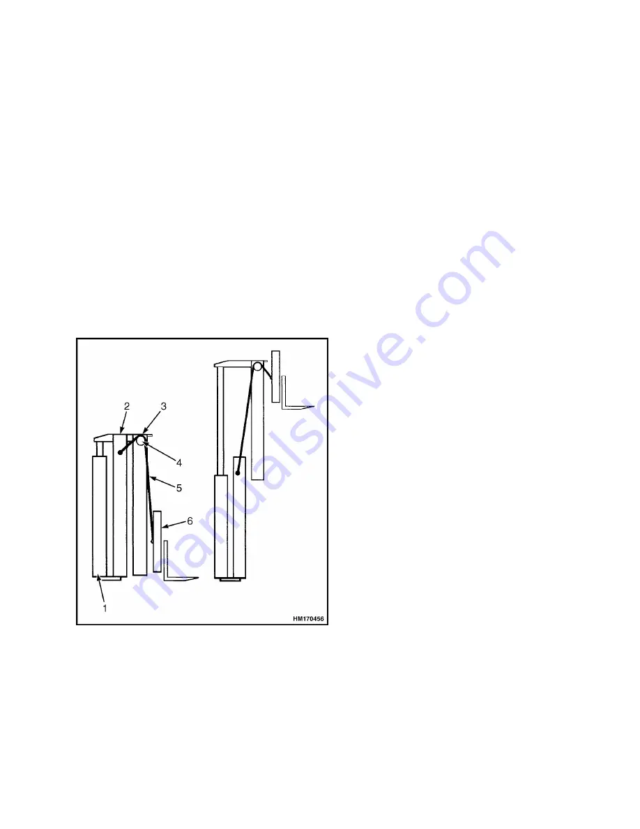
The lift cylinders are supported at the base of the
outer mast. When the cylinders extend, they push
the inner mast upwards. The chains are attached to
the outer mast and the carriage, and they run over
the chain sheaves at the top of the inner mast.
When the inner mast moves upwards, the chains
pull the carriage upwards to twice the distance that
the lift cylinders have extended. See Figure 4.
Operation
The lift cylinders extend when the hydraulic
pressure applied is sufficient to lift the combined
weight of the load, forks, carriage and inner mast.
The raised position of the mast is maintained by
hydraulically closing off the piston side of the lift
cylinders. Lowering is achieved by releasing
hydraulic pressure, which is induced by the weight
resting on the rod of the lift cylinders.
1. LIFT CYLINDERS
2. OUTER MAST
3. INNER MAST
4. CHAIN SHEAVE
5. LIFT CHAIN
6. CARRIAGE
Figure 4. Operation of a Two-Stage Mast
Lifting speed and lowering speed are controlled by
the moved position of the lift spool in the main
control valve. Maximum lifting speed is determined
by maximum pump supply. Maximum lowering
speed is determined by the lowering control valve at
the bottom of each lift cylinder.
The lowering control valve is a pressure
compensated valve. It allows an increasing flow
with increasing pressure until a preset maximum
flow is reached. The result is that similar lowering
speeds are obtained for loaded and unloaded
conditions. The primary function of the lowering
control valve is to limit the lowering speed in case of
a malfunction of the supply/return connection.
The different lift height capacities are determined
by the dimensions of the various mast assemblies.
The lowest position of the forks is determined by the
adjustment of the chain anchors.
Pilot Operated Check Valves
The lift spool in the main control valve does not seal
completely in the neutral position. To obtain zero
leakage, a pilot operated check valve is mounted in
the main control valve between lift spool and lift
cylinder. See Figure 5.
When raising the mast, oil supply will pass through
a check valve in the pilot operated check valve. To
lower the mast, the pilot operated check valve must
be moved into the open position.
The position of the pilot operated check valve, is
determined by oil pressure at the cylinder side of
the check valve, and by the combined force of a
spring and the oil pressure at the pilot side of the
check valve. Spring force will keep the check valve
closed when equal pressures exist at the pilot side
and cylinder side of the check valve.
The pilot operated check valve opens when pressure
is removed from the pilot side of the check valve,
which connects with the selector valve. The selector
valve opens when the lift spool has moved into the
lowering position, which allows pilot pressure from
the spool to reach the selector valve. After the
selector valve has opened and drained pilot pressure
from the pilot operated check valve, the oil from the
lift cylinders will drain through the check valve and
lift spool to the tank.
4000 SRM 1664
Description And Operation
3
Содержание A238
Страница 1: ...MAST H16XM9 12 H18XM 7 5 9 H360 36HD H360 48HD A238 B238 PART NO 4097319 4000 SRM 1664...
Страница 21: ......


