


These meters can be examined more closely or reset
by a Service Technician using the procedures de-
scribed in the Status Menu section.
ALERT SCREENS
There are two types of alert screens, Fault Screens
(failure indication screens) and Interlock Notifica-
tion Screens. Both types of alert screens are tempo-
rary in nature because the system immediately re-
stores the original screen after a key press or other
action removes the problem.
When the system detects an active failure, the dis-
play changes to a Fault Screen which flashes a
fault code, the Wrench Icon, and other icons to indi-
cate the problem, similar to the example shown in
Figure 14. As it is displayed, the alert screen
flashes to draw the user's attention. Pressing either
the Scroll Back Key (
◂
—) or Scroll Forward
Key (—
▸
) after the alert screen appears causes the
system to return to the last screen displayed.
1. EXAMPLE FAULT CODE
2. WRENCH ICON
3. ICONS OF DISABLED/PERFORMANCE LIMI-
TED FUNCTIONS
Figure 14. Example Fault Screen
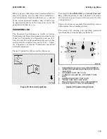
The Interlock Notification Screen appears when-
ever the operator tries to apply an input that is not
available because one or more interlock conditions
have not been met. For example, if the operator is
not seated and tries to apply the accelerator pedal,
the system will switch from the Operating Screen
to an alert screen showing the Seatbelt Icon, as
shown in Figure 15.
Figure 15. Example Interlock Alert Screen
In this example, if the operator releases the acceler-
ator pedal, the system will change the screen back
to the Operating Screen. Alternatively, the operator
can press either the Scroll Back Key or the
Scroll Forward Key to go to a top-level menu but
the accelerator pedal input will still be unavailable
because the interlock condition has not been met.
2200 SRM 1336
System Off/Alert Screens
65
Содержание A1.3-1.5XNT
Страница 6: ... THE QUALITY KEEPERS HYSTER APPROVED PARTS ...
Страница 9: ...Figure 3 Technician Flowchart Sheet 1 of 4 2200 SRM 1336 Menu Flowchart 3 ...
Страница 10: ...Figure 3 Technician Flowchart Sheet 2 of 4 Menu Flowchart 2200 SRM 1336 4 ...
Страница 11: ...Figure 3 Technician Flowchart Sheet 3 of 4 2200 SRM 1336 Menu Flowchart 5 ...
Страница 12: ...Figure 3 Technician Flowchart Sheet 4 of 4 Menu Flowchart 2200 SRM 1336 6 ...
Страница 123: ......
Страница 124: ...TECHNICAL PUBLICATIONS 2200 SRM 1336 2 14 8 13 4 13 12 12 3 12 12 11 ...


