CONNECTING SEQUENCED GATES
Sequenced gates are slightly different than dual or
interlocked gates. When two gate operators are
connected as sequenced gates, a faster “Traffic
Control Gate” operator (i.e. gate or crash wedge)
and a slower “Security Gate” operator (slide,
swing, or vertical lift gate) operate in sequence to
help prevent tailgating by unauthorized vehicles.
Both operators open (Security Gate first followed
by the Traffic Control Gate) and allow a vehicle
through, but the faster moving Traffic Control
Gate closes quickly once its reset/center loop and
all obstruction loops are cleared. Upon reaching
its closed limit, the Traffic Control Gate signals
the Security Gate to close. Note that all shared
vehicle detector loops must be cleared before
the Security Gate closes.
The Smart DC Controller (SDC) provides the
sequenced gate connections and programming
features, and the SDC software establishes
the communication protocols when wiring the
sequenced gate operators.
NOTICE
An emergency open or close overrides the
gate sequencing and acts upon both gates
simultaneously.
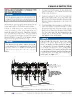
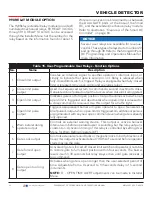
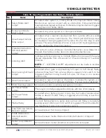
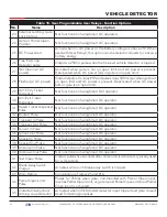
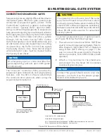
To connect a sequenced pair of gate operators,
Figure 58 follow the following steps:
1.
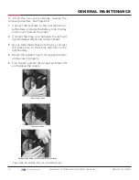
The same wire connections (DUAL GATE) are
used in connecting sequenced gates. Refer to
Wire Diagram: Interlocked Pair of Operators
using DUAL GATE Wiring on page 77. Be
sure to connect the wires in pairs to the same
terminal ports (A-A, B-B, COM-COM) on both
operators.
2.
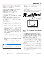
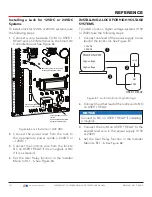
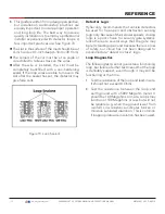
Attach a ring terminal to the shield wire
and connect it to the Smart DC Controller’s
convenient ground screw.
CAUTION
The operators do not have to be of the same
type, but both need to have the most current
and up-to-date software version installed. The
inherent SDC software integrates seamlessly
between operators and software protocols and
allows RS-485 communication for networked
security systems
NOTICE
Connect the ground shield wire to only one
operator, not both. Use the proper gauge
twisted and shielded triple wire.
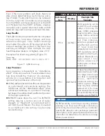
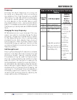
Figure 58. Sequenced Menu Setup
Status Display
User Menu
Installer Menu
Sequence Gate
Status Display
CT 0 or HC 1
FD 0
SG 0
To access the Installer Menu,
press and hold Reset & Open,
and then release them.
Press Select so “SG” characters blink.
Press Next to change the display:
SG 1 = Sequenced Gate #1 configuration
SG 2 = Sequenced Gate #2 configuration
NOTE:
Set both operators on the site to the
same number.
Press Menu twice at
the gate status display.
Press Next until
“SG” appears.
Press Select again and a gate
status display appears indicating
the sequenced gate entry had been
accepted.
BI-PARTING/DUAL GATE SYSTEM
101
| www.hysecurity.com
SWINGSMART DC PROGRAMMING AND OPERATIONS MANUAL
MX3640-01 REV. D ©2018
Содержание SwingSmart DC 20
Страница 2: ...2 www hysecurity com SWINGSMART DC PROGRAMMING AND OPERATIONS MANUAL MX3640 01 REV D 2018...
Страница 24: ...SAFETY INFORMATION 24 www hysecurity com SWINGSMART DC PROGRAMMING AND OPERATIONS MANUAL MX3640 01 REV D 2018...
Страница 138: ...NOTES 138 www hysecurity com SWINGSMART DC PROGRAMMING AND OPERATIONS MANUAL MX3640 01 REV D 2018...
Страница 139: ...NOTES 139 www hysecurity com SWINGSMART DC PROGRAMMING AND OPERATIONS MANUAL MX3640 01 REV D 2018...

