background image


User manual R5 

PSC

2

.

400


- 2 - 

Table of contents 


Product description .............................................................................................................. 3


Type remarks...................................................................................................................... 3


Features .............................................................................................................................. 3


Applications........................................................................................................................ 3


Connections........................................................................................................................ 4


System information ............................................................................................................. 6


Description.......................................................................................................................... 6


Audio performance data ................................................................................................... 6


Hardware Architecture ...................................................................................................... 7


Digital audio input............................................................................................................. 7


Controllers .......................................................................................................................... 7


Clip limiter .......................................................................................................................... 7


Product overview................................................................................................................... 8


Hardware part .................................................................................................................... 8


Software installation ......................................................................................................... 9


Control panel ................................................................................................................... 9


Filter design...................................................................................................................10


Graph Area.....................................................................................................................11


Filter Definition Area ....................................................................................................11


Settings Window...........................................................................................................11


Work flow .......................................................................................................................11


Measurement ................................................................................................................11


Designing filters............................................................................................................13


Download ..........................................................................................................................14


Firmware update .................................................................................................................14


Safety precautions..............................................................................................................15


Instructions For Installation..............................................................................................15


Recommended Operating Conditions for the SMPS....................................................16


General Performance data for the SMPS ......................................................................16


Mains selection ...................................................................................................................17


Technical data .....................................................................................................................18


Содержание PSC2.400

Страница 1: ...Hypex Electronics BV Kattegat 8 9723 JP Groningen The Netherlands 31 50 526 4993 sales hypex nl www hypex nl User Manual Powered Speaker Controller PSC2 400...

Страница 2: ...lers 7 Clip limiter 7 Product overview 8 Hardware part 8 Software installation 9 Control panel 9 Filter design 10 Graph Area 11 Filter Definition Area 11 Settings Window 11 Work flow 11 Measurement 11...

Страница 3: ...ith 2 modules it is also possible to set up a 3 channel system with one module for the separate Subwoofer and a second module for the top in a 2 channel system Use only only only only a version 1 4 or...

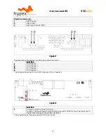
Страница 4: ...ections Figure 1 Overview of the connections on the front of the PSC2 400 Function 1 USB input 2 Select button 3 Preset LED s 4 Clip detect LED 5 Analogue Link 6 Analogue Audio Input 10 Power input 11...

Страница 5: ...n 1 1 1 1 J16 Speaker 2 2 2 2 J14 Speaker 3 3 3 3 J17 Speaker 4 4 4 4 J15 Speaker For bridged mode use J14 and J15 Signal on J14 is inverted Figure Figure Figure Figure 3 3 3 3 Function Function Funct...

Страница 6: ...Electronics A PC controls the PSC2 through the USB port This connection is used to upload the configuration and filter settings It will also be possible to update the firmware through USB Audio perfo...

Страница 7: ...ive When the module is set to Auto input select in the control panel on the computer the input source is automatically switched to digital when present If the digital audio is stopped the source will...

Страница 8: ...or as a one channel bridged version for more power This is selected in software The module can store up to 4 presets A preset holds the complete filter settings of both channels By this the user is ab...

Страница 9: ...the control panel you see the Force input and active input groups This shows you the settings of the audio in puts and lets you control these inputs only for digital version Audio can be provided anal...

Страница 10: ...ets are installed they may be selected the module will switch to the selected preset The presets can be filled in the Filter design section Filter design When you want to make some filters for your mo...

Страница 11: ...tionally identical The top left frame is used to import response files The select button opens a file The show checkbox turns display of the measured graph on or off The Common Settings box controls g...

Страница 12: ...that the absolute gain be the same for all three measurements The filter designer computes a gain offset based on all loaded responses to centre them collectively on the vertical scale Truncating resp...

Страница 13: ...ays 3dB First order highpass HPF2 Cut off frequency asymptotically Q Second order highpass A Q of 0 71 cor responds to butterworth 0 5 corre sponds to LR2 Two identical sections with a Q of 0 71 form...

Страница 14: ...r master and slave module Under option download you can find Firmware update When this option is selected the user can select the new firmware file This is a complete hex file provided by Hypex no ada...

Страница 15: ...PS400 is mounted in a tight space there needs to be at least 6mm clearance or a layer of insulation with a minimum thick ness of 0 5mm between the top of the transformer and the housing Standard the S...

Страница 16: ...ve a minimum distance of 6mm maintain clearance with all possible conducting parts housing etc All parts enclosed by the dotted line below carry hazardous voltages This includes parts on the top and t...

Страница 17: ...be followed Before changing the mains settings disconnect the unit from the mains and allow all ca pacitors to discharge for 10 minutes before handling it Update the front plate with the updated info...

Страница 18: ...R5 PSC2 400 18 Technical data Supply voltage 230Volt AC 50Hz 10 switch able to 115Volt 60Hz Dimensions 142mmx330mmx55mm WxHxD Plate thickness 2 5mm Weight 1 1 kg Clearance 9 5mm Figure 16 Plate amp 2...

Страница 19: ...added 06 10 2009 R2 PSC2 V1 Pinout description added Clip limiter added 23 06 2010 R3 PSC2 V1 Safety instructions added Installation instructions added Mains selection added 29 06 2010 R4 PSC2 V2 Expl...

Отзывы: