Hydrotech HDF501 Series Скачать руководство пользователя страница 15

15

Operation and maintenance manual for

Hydrotech Drumfilter HDF501-series

5.2.3.Adjusting.the.level.sensor

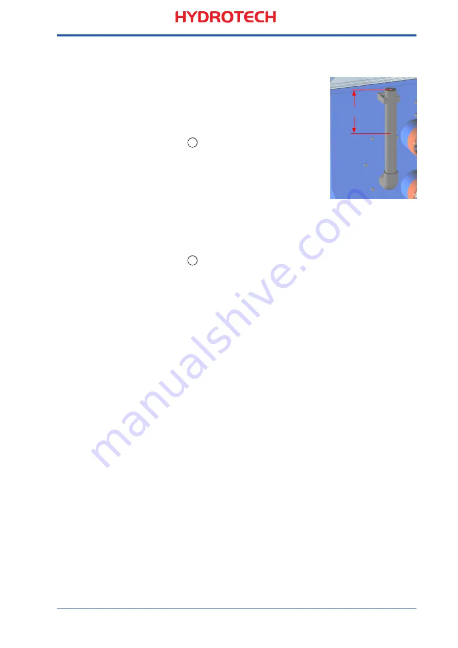
Adjust the level sensor to 230-250 mm below the

top of the level pipe. The optimal position depends 

on how turbulent the water surface is (see 

Figure 

5.5.2

). 

5.2.4.Setting.the.time.relay

A time relay (see 

5


Figure 5.2

) is used to delay 

the backwash stop when the water level is below 

the level sensor. The time relay is preset so that the 

drum is backwashed during one rotation. 
In some applications it might be necessary to 

increase the backwash time delay to avoid long 

term clogging.

5.2.5.Setting.the.level.relay

The sensitivity of the level sensor can be set from MIN. to MAX. on the level 

relay and three different sensitivity ranges can be selected on the lower level 
relay switch (see 

6

 in 

Figure 5.2

).

If the appropriate sensitivity is not within the selected range change it to 

another sensitivity range. For water with a high conductivity (= low resistance) 

chose setting 1. For water with a low conductivity (= high resistance) chose 

setting 3. Sea water, for example, has a high conductivity. 

See also appendix E, level sensors.

5.3.Backwash.system

The standard backwash nozzles (TeeJet 6505) have an equivalent opening 

size of 1.4 mm. For some applications it may be necessary to use a lower 

rinse water flow. This can be achieved by installing nozzles with a smaller 

opening size. Contact the supplier or Hydrotech for more information. 
The backwash system pressure is set to 7-8  bars.

5.4.Drum.rotation

The filter is powered by a gear motor that rotates the drum by direct drive.
Direction of rotation is marked on the motor cover.

5.5.Re-tightening.of.bolts

After  two working weeks or 80  production hours, all bolted joints must be re-

tightened.

Figure  5.5.2  

Adjusting the level sensor

230-250 mm

Содержание HDF501 Series

Страница 1: ...Operation and Maintenance Manual TYPE 1P 1FP SERIAL NO Revised 10 09 17 EN Drumfilter HDF501 series...

Страница 2: ...ECEIVING AND HANDLING 9 3 1 Receiving 9 3 2 Storage 9 3 3 Lifting 9 4 GENERAL INSTALLATION INSTRUCTIONS 10 4 1 Installation site 10 4 1 1 Outdoor installation 10 4 1 2 Foundation 10 4 2 Emergency by p...

Страница 3: ...2 1 Lubrication 19 7 2 2 Checking the slide bearing for wear 19 7 3 Filter panels 20 7 3 1 Change the filter panels 21 7 4 Drive chain not applicable for HDF501 1P 21 7 5 Gear motor 22 7 6 Rubber sea...

Страница 4: ...e manual should always be available to the personnel who work with the equipment It is important that The manual and other applicable documents are preserved during the whole life span of the equipmen...

Страница 5: ...ntial personal injury and or damage to the equipment Safety warning labels see Figure 1 1 are affixed to the Drumfilter lids to warn personnel to keep hands and fingers away from moving parts of the f...

Страница 6: ...RNING Set the safety switch to OFF 0 and lock it in the OFF position by means of a padlock before starting any work on the filter WARNING Access to the filter by unauthorised persons must be strictly...

Страница 7: ...1 series 2 HYDROTECH DRUMFILTER 12 16 20 SERIES 2 1 Overview Figure 2 1 Parts of HDF501 series INLET SIDE MOTOR SIDE Level sensor optional Control cabinet optional Back wash unit Drum Solids outlet In...

Страница 8: ...Model F Industrial model P GRP tank Drumfilter type 1 Filter with tank 2 Filter without tank Open inlet 3 Filter without tank Pipe inlet HDF 501 1FP Mejselgatan 6 235 32 Vellinge Sweden Web www hydro...

Страница 9: ...the equipment should be stored inside in a room with temperature above freezing For outdoor storage it is necessary to protect the filter from direct sunlight as the heat and UV radiation may damage t...

Страница 10: ...ional and structural strength The filter must be properly levelled in both directions see figure 4 1 600 mm wide walkways should be fitted around the filter in order to provide easy access to the filt...

Страница 11: ...ing from the sludge channel must have an inclination of at least 1 4 6 Backwash system A new rinse water pipe system should be flushed for at least 10 min before connecting it to the filter Thoroughly...

Страница 12: ...necessary to fill up the tank with water from an external source to be able to start the pump 6 When the water level inside the tank or goes above the suction pipe the pump switch should be set to 1...

Страница 13: ...tion mode see 5 in Figure 5 2 Figure 5 2 Hydrotech standard control cabinet optional The design of the control cabinet is often adapted to each application Appendix E Hydrotech control box optional Id...

Страница 14: ...ic level control With level control the drum rotation and the backwash pump is activated when the water level inside the drum reaches the level sensor If an independent rinse water supply is used the...

Страница 15: ...in Figure 5 2 If the appropriate sensitivity is not within the selected range change it to another sensitivity range For water with a high conductivity low resistance chose setting 1 For water with a...

Страница 16: ...croscreen cloth fitted on the outside of the filter panels while the clean water passes through the cloth to the outside of the drum 3 AUTO mode The solids collected on the inside of the filter cloth...

Страница 17: ...ater cannot pass through 4 Remove the bayonet nut by turning it of a revolution counter clockwise Be careful not to loose the rubber seal 5 Clean the nozzle with compressed air or a plastic brush Neve...

Страница 18: ...ater When a nozzle becomes worn out the nozzle tip opening becomes enlarged see Figure 7 1 2c This leads to a less efficient back wash changed dispersion and higher rinse water consumption Therefore i...

Страница 19: ...s 7 2 Bearings 7 2 1 Lubrication The drum has a plastic slide bearing which does not need to be greased 7 2 2 Checking the slide bearing for wear Every sixth month the slide bearing must be checked fo...

Страница 20: ...with a wide opening size and a cleaning pressure of max 80 bar Never hold the cleaning nozzle directly to the filter media Long term clogging of the filter cloth may be caused by iron calcium or orga...

Страница 21: ...n of the strap section to the end of the filter element Press down the strap and filter element together over the holes of the angle iron that fit over the pin bolts See figure 7 3 1 d Be careful not...

Страница 22: ...r sealing between the filter frame and the drum must be checked every year for wear and leakage The rubber sealing should tighten against the inside of the drum 7 7 Backwash strainer A backwash strain...

Страница 23: ...safety switch to OFF 0 and lock it in the OFF position by means of a padlock before starting any work on the filter Every week or other interval based on experience for the actual application Wash th...

Страница 24: ...ere is power to the relay C Replace the defective level relay D The UP DOWN switch is in the UP position D Set the UP DOWN switch to the DOWN position 2 The filter does not stop after the time set on...

Страница 25: ...25 Operation and maintenance manual for Hydrotech Drumfilter HDF501 series...

Страница 26: ...AB A Veolia Solutions Technologies Company Mejselgatan 6 235 32 Vellinge Sweden Phone 46 0 40 42 95 30 Fax 46 0 40 42 95 31 E mail mailbox hydrotech se Web site www hydrotech se Copyright All rights...

Отзывы: