8
9
VI. PUMP INSTallaTION
1. The pump shall be installed in a well ventilated, free of freezing, free of sun an rain.
2. The pipeline of suction inlet shall be as short as possible. An elbow shall be used in
the corner to reduce the loss of pipeline.
3. It is better that the suction pipe should be larger than the inlet of the pump. Connect
it with the pump after changing the diameter.
4. The suction pipe shall not be higher in the front and lower in the rear to prevent the
air locks.
5. The suction end of the suction inlet shall be fully immerged into the liquid and ensure
the joints to be well scaled to prevent from air in.
6. The mounting height of the pump shall not exceed its allowable suction height.
7. To avoid the distorsion of the pump due to the gravitation from the pipeline, suction
pipeline ans discharge pipeline shall have separate support device.
8. Pressure gauge shall be installed on the outlet of the pump for observation and
controlling the operation of the pump.
9. In case suction liquid level is lower than the suction inlet of the pump. the bottom
valve shall be installed.
10. The motor shall be earthed. Electric devices shall be ensured not to be damaged
by phase shortage, unstable voltage and overload.
WARNING - Electrical connection and safety devices
· The pump units should be connected to the power supply by the appropriately rated
power cables according to the motor ratings.
· The pump units should always be equipped with safety devices as required in
the standars (EN 809 and / or EN 60204-1) as well as by the national rules of the
country where the pump is used.
· Despite the rules of any country, the power supply to the pump unit must be
equipped with at least following electrical safety devices with appropriate ratings:
- Emergency switch
- Circuit breaker (as a supply disconnecting (isolating) device as well as an
overcurrent protective device)
- Motor overload protection
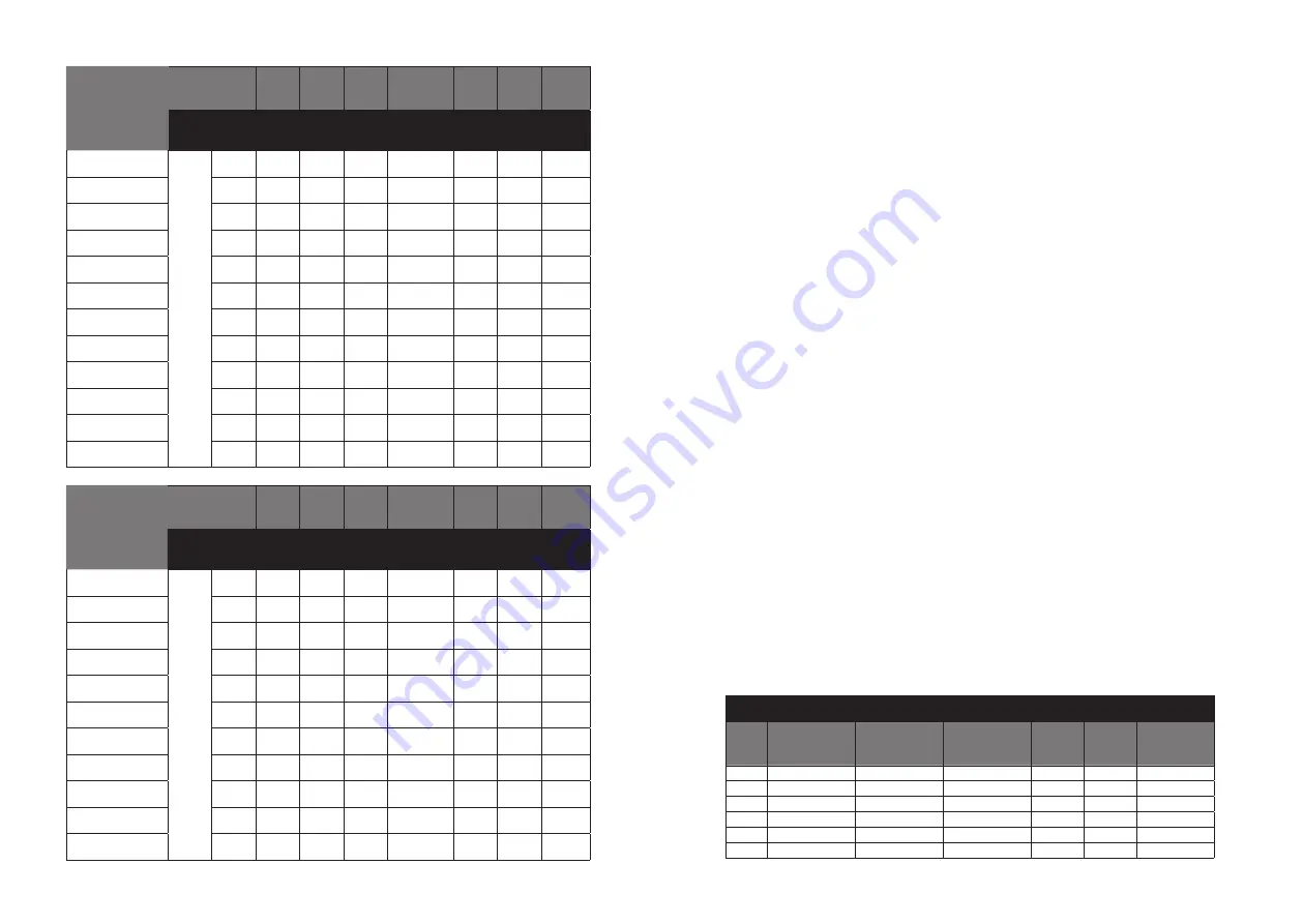
The following table is for suggestion:
Model
Motor
L1
L2
L3
H
(3HP/1HP)
DN S
DN D Weight
Phase Power
(KW)
(mm)
Inlet
Outlet
kg
MX, MN 60/0.37
3PH
1PH
0.37
328
113
51
216/230
G1-1/4
G1
10
MX, MN 60/0.55
0.55
328
113
51
216/230
G1-1/4
G1
12
MX, MN 60/0.75
0.75
361
113
51
223/245
G1-1/4
G1
14
MX, MN 100/0.55
0.55
328
113
51
216/230
G1-1/4
G1
12
MX, MN 100/1.1
1.1
361
113
51
223/245
G1-1/4
G1
16
MX, MN 160/0.75
0.75
375
127
54
223/245
G1-1/2 G1-1/4
14
MX, MN 160/1.1
1.1
375
127
54
223/245
G1-1/2 G1-1/4
16
MX, MN 250/1.1
1.1
375
127
54
223/245
G1-1/2 G1-1/4
16
MX, MN 250/1.5
1.5
415
127
54
232/253
G1-1/2 G1-1/4
20
MX, MN 250/2.2
2.2
415
127
54
232/253
G1-1/2 G1-1/4
23
MX, MN 330/1.5
1.5
415
127
54
232/253
G1-1/2 G1-1/4
20
MX, MN 330/2.2
2.2
415
127
54
232/253
G2
G1-1/4
23
Model
Motor
L1
L2
L3
H
(3HP/1HP)
DN S
DN D Weight
Phase Power
(KW)
(mm)
Inlet
Outlet
kg
MX, MN 100/0.75
3PH
1PH
0.75
361
113
51
223/245
G1-1/4
G1
14
MX, MN 100/1.1
1.1
361
113
51
223/245
G1-1/4
G1
14
MX, MN 100/1.5
1.5
401
113
51
232/253
G1-1/4
G1
20
MX, MN 160/1.1
1.1
375
127
54
223/245
G1-1/2 G1-1/4
16
MX, MN 160/1.5
1.5
415
127
54
232/253
G1-1/2 G1-1/4
20
MX, MN 160/2.2
2.2
415
127
54
232/253
G1-1/2 G1-1/4
23
MX, MN 250/1.1
1.1
375
127
54
223/245
G1-1/2 G1-1/4
16
MX, MN 250/1.5
1.5
415
127
54
232/253
G1-1/2 G1-1/4
20
MX, MN 250/2.2
2.2
415
127
54
232/253
G1-1/2 G1-1/4
23
MX, MN 330/1.5
1.5
415
127
54
232/253
G2
G1-1/4
20
MX, MN 330/2.2
2.2
415
127
54
232/253
G2
G1-1/4
23
380V 50Hz/60Hz
No.
Power input
(kW)
Cable
connection
Input current
(A)
Cable
spec
(mm
2
)
Circuit
breaker
(A)
Thermal
protector
(A)
1
0.37
Y
1.
0.75
5
1.2
2
0.55
Y
1.4
0.75
5
1.7
3
0.75
Y
1.8
0.75
5
2.2
4
1.1
Y
2.6
1
5
3.1
6
1.5
Y
3.5
1
10
4.2
8
2.2
Y
4.9
1.5
10
5.9
Содержание MDROO Series
Страница 8: ...14 15 Notes ...


