310-0510 IHT
13
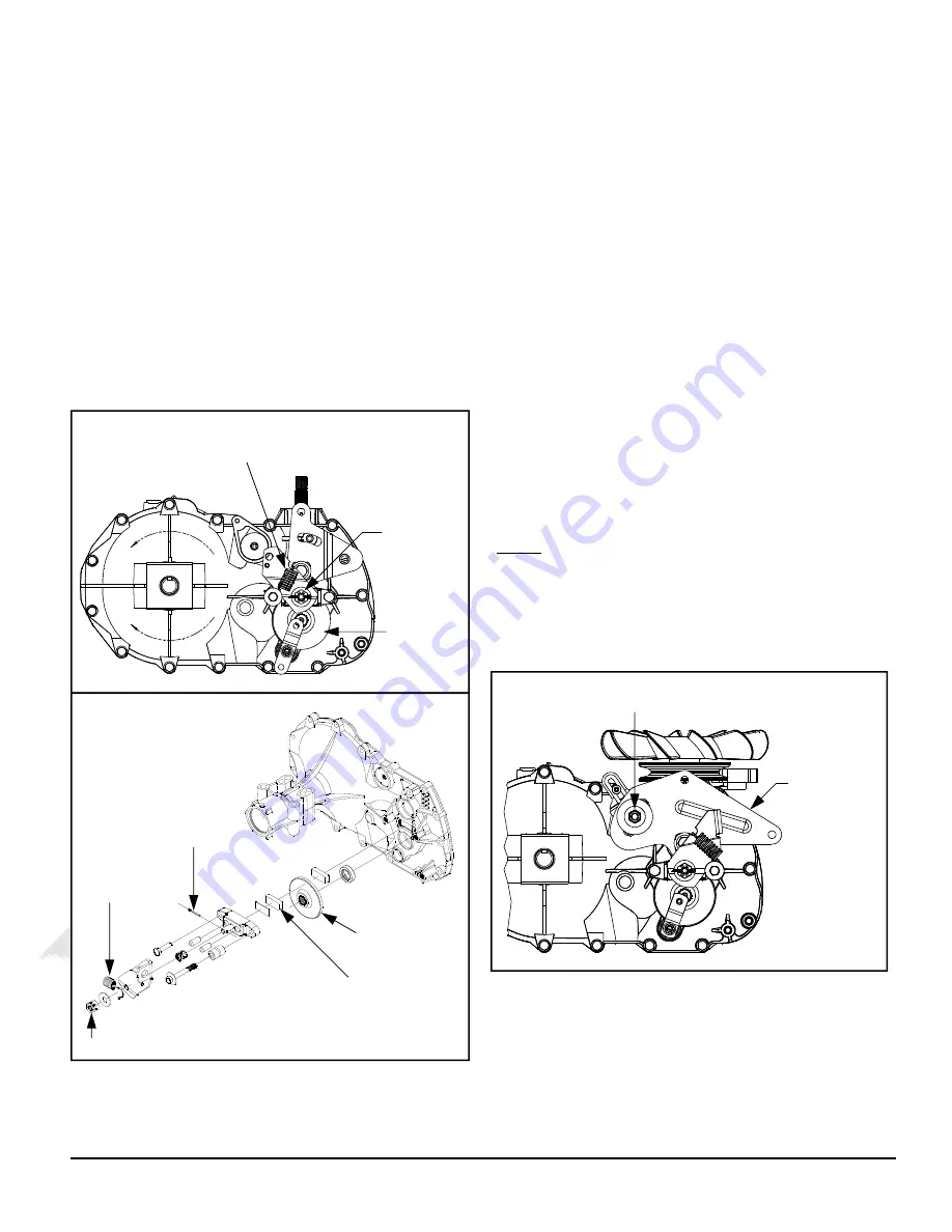
BRAKE SETTING
1. Remove the brake arm bias spring, and
then the cotter pin securing the brake castle
nut.
2. Insert a 0.015" feeler gage between the
brake disc and top brake puck, and then set
the brake by finger tightening or loosening
the castle nut.
3. Install a new cotter pin to secure the castle
nut, and then install the brake arm bias
spring.
BRAKE CHECKING
When checking the brake puck/rotor gap, the
gap should be 0.010-0.030 inches (0.254-
0.762 mm).
FRICTION PACK ADJUSTMENT
The friction pack dampens or holds the opera-
tor control lever in its desired position.
Adjustment for the amount of drag or holding
force can be made by turning the friction pack
nut in or out.
Adjustments should be made in no more than
1/4 turn increments.
Over-tightening will result in difficulty or inability
of the operator to move the control lever.
Note: The factory setting for the friction pack is
tightening of the friction pack nut to 100 in-lbs
(11 Nm) torque. The friction pack nut is then
backed off per the vehicle manufacturer’s
specifications.
BRAKE MAINTENANCE
Figure 6. Brake Components
Figure 7. Friction Pack
CONTROL ARM
FRICTION PACK NUT
BRAKE ARM
BIAS SPRING
CASTLE NUT
BRAKE DISC
BRAKE DISC
CASTLE NUT
BRAKE ARM
BIAS SPRING
COTTER PIN
TOP BRAKE PUCK
Содержание 310-0510
Страница 1: ...310 0510 0610 0710 Integrated Hydrostatic Transaxle Service and Repair Manual BLN 51260 Dec 2008 ...
Страница 7: ...310 0510 IHT 5 MODEL RECOGNITION 618 0319 166768 104 1760 173839 036932 618 0389A ...
Страница 32: ...310 0510 IHT 30 310 0710 EXPLODED VIEW ...
Страница 34: ...310 0510 IHT 32 310 0610 EXPLODED VIEW ...
Страница 36: ...310 0510 IHT 34 310 0510 EXPLODED VIEW 6 SEALANT 57 20W 50 OIL 127 SEAL O RING KIT ...
Страница 40: ...310 0510 IHT 38 2008 HYDRO GEAR Printed in U S A Rev P2 ...


