background image

Description of CANopen-Interface 

HYDAC ELECTRONIC GMBH


07.10.2010 

Mat. No. 669824 

Page 48 of 63 

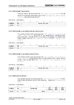
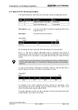
8.12 Object 1018h: Identity Object 

 
This object provides general identification information of the CANopen device. 
 

Index 

Sub-Index 

Comment 

Type 

1018h 

highest sub-index supported 

 Unsigned8 

1

Vendor-ID  

Unsigned32 

2

Product-Code  

Unsigned32 

3

Order-No.  

Unsigned32 

4

Serial-No.  

Unsigned32 

Sub-index0

: The entry at sub-index 0 contains the largest Sub-Index that is supported: 


Value = 4. 


Sub-index1:  

Contains the Vendor-ID of the manufacturer. The Vendor-ID for 
HYDAC-ELECTRONIC GmbH is 218 = 0xDA. 


Sub-index2:  

Provides information about the product code with 


the associated device profile. 


Sub-index3:  

Provides information about the order number. 


Sub-index4:  

Provides information about the serial number. 


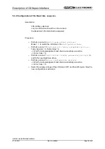
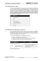
8.13 Objekt 1F80: NMT-Startup (read / write) 

 
Will be set bit 2, automatically by reaching the “Pre-operational” state, will be change 
into “Operational” state. Permitted values are: 0x8 and 0xC.  
 

Index 

Subindex 

Comment 

Type 

1F80h 0 

NMT-Startup 


Unsigned32 

Bit 2 =  0 

Automatically change into operational mode 

 
Bit 2 =  1 

No automatically change into operational mode 

Содержание HLT 1100 Series

Страница 1: ...stelle Linear Transducer Series HLT 1100 with CANopen Interface Zusätzliche Sicherheitshinweise Additional safety instructions Installation Installation Inbetriebnahme Commissioning Konfiguration Parametrierung Configuration Parameterization Fehlerursachen und Abhilfen Causes of faults and remedies Software Support CD Software Support CD Mat Nr 3505546 Mat No 3505546 ...

Страница 2: ...heberrechtsschutz Dieses Handbuch einschließlich den darin enthaltenen Abbildungen ist urheberrechtlich geschützt Drittanwendungen dieses Handbuchs welche von den urheberrechtlichen Bestimmungen abweichen sind verboten Die Reproduktion Übersetzung sowie die elektronische und fotografische Archivierung und Veränderung bedarf der schriftlichen Genehmigung durch den Hersteller Zuwiderhandlungen verpf...

Страница 3: ...ätekontrolle 21 4 6 1 2 NMT Dienste zur Verbindungsüberwachung 22 4 7 Layer setting services LSS und Protokolle 23 4 7 1 LSS Modes und Dienste 24 4 7 2 Übertragung von LSS Diensten 26 4 7 2 1 LSS Nachrichtenformat 26 4 7 3 Switch mode Protokolle 26 4 7 3 1 Switch mode global Protokoll 26 4 7 3 2 Switch mode selective Protokoll 27 4 7 4 Configuration Protokolle 28 4 7 4 1 Configure Node Id Protokol...

Страница 4: ...00h Gerätetyp 43 8 2 Objekt 1001h Fehlerregister 43 8 3 Objekt 1003h Vordefiniertes Fehlerfeld 44 8 4 Objekt 1005h COB ID SYNC Nachricht 44 8 5 Objekt 1008h Hersteller Gerätenamen 45 8 6 Objekt 1009h Hersteller Hardwareversion 45 8 7 Objekt 100Ah Hersteller Softwareversion 45 8 8 Objekt 100Ch Guard Time Überwachungszeit 45 8 9 Objekt 100Dh Life Time Faktor Zeitdauer Faktor 45 8 10 Objekt 1010h Par...

Страница 5: ...oftwareversion 56 9 14 Objekt 6508h Betriebszeit 56 9 15 Objekt 650Ah Modul Identifizierung 56 9 16 Objekt 650Bh Serien Nummer 56 9 17 Objekt 650Ch Offsetwert 56 10 Emergency Meldung 57 11 Übertragung des Mess System Positionswertes 58 12 Fehlerursachen und Abhilfen 60 12 1 SDO Fehlercodes 60 12 2 Emergency Fehlercodes 60 12 2 1 Objekt 1001h Fehlerregister 61 12 2 2 Objekt 1003h Vordefiniertes Feh...

Страница 6: ...ine Ergänzung zu anderen Dokumentationen wie z B Produktdatenblätter Maßzeichnungen Prospekte und der Montageanleitung etc dar Das Benutzerhandbuch kann kundenspezifisch im Lieferumfang enthalten sein oder kann auch separat angefordert werden 1 1 Geltungsbereich Dieses Benutzerhandbuch gilt ausschließlich für folgende Mess System Baureihen mit CANopen Schnittstelle HLT 1100 Die Produkte sind durch...

Страница 7: ...DS 202 3 V1 1 CMS Verschlüsselungsregeln Februar 1996 7 CiA DS 203 1 V1 1 NMT Service Spezifikation Februar 1996 8 CiA DS 203 2 V1 1 NMT Protokoll Spezifikation Februar 1996 9 CiA DS 204 1 V1 1 DBT Service Spezifikation Februar 1996 10 CiA DS 204 2 V1 1 DBT Protokoll Spezifikation Februar 1996 11 CiA DS 205 1 V1 1 LMT Service Spezifikation Februar 1996 12 CiA DS 205 2 V1 1 LMT Protokoll Spezifikat...

Страница 8: ...nwendungsschicht im CAN Referenz Model COB Communication Object CAN Message Übertragungseinheit im CAN Netzwerk Daten müssen in einem COB durch das CAN Netzwerk gesendet werden COB ID COB Identifier Eindeutige Zuordnung des COB Der Identifier bestimmt die Priorität des COB s im Busverkehr DBT Distributor Eines der Serviceelemente in der Anwendungs schicht im CAN Referenz Model Es liegt in der Vera...

Страница 9: ... und Anwendungstipps des verwen deten Produkts 2 2 Ergänzende Hinweise zur bestimmungsgemäßen Verwendung Das Mess System ist ausgelegt für den Betrieb an CANopen Netzwerken nach dem internationalen Standard ISO DIS 11898 und 11519 1 bis max 1 MBaud Das Profil entspricht dem CANopen Device Profile für Encoder CiA DS 406 V2 0A Die technischen Richtlinien zum Aufbau des CANopen Netzwerks der CAN Nutz...

Страница 10: ... aufbewahrt werden Das mit Tätigkeiten am Mess System beauftragte Personal muss vor Arbeits beginn die Montageanleitung insbesondere das Kapitel Grundlegende Sicherheitshinweise und dieses Benutzerhandbuch insbesondere das Kapitel Zusätzliche Sicherheitshinweise gelesen und verstanden haben Dies gilt in besonderem Maße für nur gelegentlich z B bei der Parametrierung des Mess Systems tätig werdende...

Страница 11: ...it 16 Bit Integer CANopen EN 50325 4 Busankopplung ISO 11898 1 ISO 11898 2 CAN Spezifikation 2 0A 11 Bit Identifier Kommunikations Profil CiA DS 301 V4 2 Geräte Profil CiA DS 406 V3 2 LSS CiA DS 305 V2 2 Node ID 1 127 Baudrate 20 50 125 250 500 800 1000 kbit s Anschluss Kupferleitung 4 x 0 5 mm Besondere Merkmale Programmierung nachfolgender Parameter über den CAN BUS Knotenadresse Baudrate Zählri...

Страница 12: ...ISO 11898 2 Diese werden in der Automatisierungstechnik durch die Empfehlungen des CiA Industrieverbandes hinsichtlich der Steckerbelegung Übertragungsraten erweitert Im Bereich der Anwendungsschicht hat CiA den Standard CAL CAN Application Layer hervorgebracht Abbildung 1 CANopen eingeordnet im ISO OSI Schichtenmodell Bei CANopen wurde zunächst das Kommunikationsprofil sowie eine Bauanleitung für...

Страница 13: ...nander austauschen Hierbei werden Echtzeitdaten z B Positionswert und Parameterdaten z B Zählrichtung unterschieden CANopen ordnet diesen vom Charakter her völlig unterschiedlichen Datenarten jeweils passende Kommunikationselemente zu Abbildung 2 Kommunikationsprofil Special Function Object SFO Synchronization SYNC Emergency EMCY Protokoll Network Management Object NMO z B Life Node Guarding Boot ...

Страница 14: ...e Daten Objekt SDO Service Daten Objekte managen den Parameterdatenaustausch wie z B das azyklische Ausführen der Presetfunktion Für Parameterdaten beliebiger Größe steht mit dem SDO ein leistungsfähiger Kommunikationsmechanismus zur Verfügung Hierfür wird zwischen dem Konfigurationsmaster und den angeschlossenen Geräten ein Servicedatenkanal für Parameterkommunikation ausgebildet Die Geräteparame...

Страница 15: ...glich sind Abbildung 4 Aufbau des Objektverzeichnisses 4 4 CANopen Default Identifier COB ID CANopen Geräte können ohne Konfiguration in ein CANopen Netzwerk eingesetzt werden Lediglich die Einstellung einer Busadresse und der Baudrate ist erforderlich Aus dieser Knotenadresse leitet sich die Identifierzuordnung für die Kommunikationskanäle ab COB Identifier Funktions Code Node ID 10 0 1 2 3 4 1 2...

Страница 16: ...O Nachrichtenformat Der maximal 8 Byte lange Datenbereich einer CAN Nachricht wird von einem SDO wie folgt belegt CCD Index Subinde x Daten Byte 0 Byte 1 Low Byte 2 High Byte 3 Byte 4 Byte 5 Byte 6 Byte 7 Tabelle 2 SDO Nachricht Der Kommando Code CCD identifiziert bei der SDO Request ob gelesen oder geschrieben werden soll Bei einem Schreibauftrag wird zusätzlich die Anzahl der zu schreibenden Byt...

Страница 17: ... Datensegmente es sich handelt und wie viele Bytes gelesen werden können Mit nachfolgenden Leseanforderungen können dann die einzelnen Datensegmente gelesen werden Ein Datensegment besteht jeweils aus 7 Bytes Beispiel für das Lesen eines Datensegmentes Telegramm 1 CCD Bedeutung Gültig für 0x40 Leseanforderung Einleitung SDO Request 0x41 1 Datensegment vorhanden Die Anzahl der zu lesenden Bytes ste...

Страница 18: ...Lese SDO Telegramm muss an den Slave gesendet werden Der Slave antwortet mit folgendem Telegramm Antwort Protokoll Format COB Identifier 580h Node ID Lese SDO s Byte 0 1 2 3 4 5 6 7 Inhalt Code Index Sub index Daten 0 Daten 1 Daten 2 Daten 3 4xh Low High Byte Daten Daten Daten Daten Format Byte 0 MSB LSB 7 6 5 4 3 2 1 0 0 1 0 0 n 1 1 n Anzahl der Datenbytes Bytes 4 7 welche keine Daten beinhalten ...

Страница 19: ... 0 0 0 Format Byte 0 MSB LSB 7 6 5 4 3 2 1 0 0 0 1 0 n 1 1 n Anzahl der Datenbytes Bytes 4 7 welche keine Daten beinhalten Wenn nur 1 Datenbyte Daten 0 Daten enthält ist der Wert von Byte 0 2Fh Das Schreibe SDO Telegramm muss an den Slave gesendet werden Der Slave antwortet mit folgendem Telegramm Antwort Protokoll Format COB Identifier 580h Node ID Lese SDO s Byte 0 1 2 3 4 5 6 7 Inhalt Code Inde...

Страница 20: ...dem Einschalten zunächst im Vor Betriebszustand 2 Stop 14 9 2 3 4 7 5 8 6 Power ON oder Hardware Reset 13 12 10 11 1 Initialisierung Vor Betriebszutand Betriebszustand Abbildung 5 Boot Up Mechanismus des Netzwerkmanagements Zustand Beschreibung 1 Automatische Initialisierung nach dem Einschalten 2 Beendigung der Initialisierung Vor Betriebszustand 3 6 Start_Remote_Node Betriebszustand 4 7 Enter_PR...

Страница 21: ...D Byte 0 Byte 1 Folgende Kommandos sind definiert CCD Bedeutung Zustand Automatische Initialisierung nach dem Einschalten 1 Beendigung der Initialisierung PRE OPERATIONAL 2 0x01 Start Remote Node Teilnehmer soll in den Zustand OPERATIONAL wechseln und damit den normalen Netzbetrieb starten 3 6 0x02 Stop Remote Node Teilnehmer soll in den Zustand STOPPED übergehen und damit seine Kommunikation stop...

Страница 22: ...ispiel 0x85 0x05 0x85 kein Fehler 0x85 0x05 0x05 Fehler Ist zusätzlich das Life Guarding aktiv erwartet der NMT Slave innerhalb eines bestimmten Zeitintervalls eine derartige Zustandsabfrage durch den NMT Master Ist dies nicht der Fall wechselt der Slave in den PRE OPERATIONAL Zustand Die NMT Dienste zur Verbindungsüberwachung verwenden den Funktionscode 1110 bin also die COB ID 0x700 Node ID Inde...

Страница 23: ...enste Switch mode services Y Switch mode selective einen bestimmten LSS Slave ansprechen Y Switch mode global alle LSS Slaves ansprechen Configuration services Y Configure Node ID Node ID konfigurieren Y Configure bit timing parameters Baudrate konfigurieren Y Activate bit timing parameters Baudrate aktivieren Y Store configured parameters konfigurierte Parameter speichern Inquiry services Y Inqui...

Страница 24: ...ung des FSAs an 1 LSS waiting Unterstützung aller Dienste wie unten angegeben 2 LSS configuration Unterstützung aller Dienste wie unten angegeben 3 Final Pseudo Zustand zeigt die Deaktivierung des FSAs an Abbildung 6 LSS Modes Zustandsverhalten der unterstützten Dienste Dienste Waiting Configuration Switch mode global Ja Ja Switch mode selective Ja Nein Activate bit timing parameters Nein Ja Confi...

Страница 25: ...S switch state global Kommando mit Parameter configuration_switch oder switch state selective Kommando keine 3 LSS switch state global Kommando mit Parameter waiting_switch keine 4 Automatischer Übergang wenn eine ungültige Node ID geändert wurde und die neue Node ID erfolgreich im nichtflüchtigen Speicher abgelegt werden konnte UND der Zustand LSS waiting angefordert wurde keine Sobald das LSS FS...

Страница 26: ...le 6 COB IDs für LSS Services 4 7 2 1 LSS Nachrichtenformat Der maximal 8 Byte lange Datenbereich einer CAN Nachricht wird von einem LSS Dienst wie folgt belegt CS Daten Byte 0 Byte 1 Byte 2 Byte 3 Byte 4 Byte 5 Byte 6 Byte 7 Tabelle 7 LSS Nachricht Byte 0 enthält die Command Specifier CS danach folgen 7 Byte für die Daten 4 7 3 Switch mode Protokolle 4 7 3 1 Switch mode global Protokoll Das angeg...

Страница 27: ...e entsprechen LSS Master LSS Slave 0 1 2 3 4 5 6 7 COB ID CS Vendor Id Reserved by CiA 0x7E5 64 LSB MSB 0 1 2 3 4 5 6 7 COB ID CS Product Code Reserved by CiA 0x7E5 65 LSB MSB 0 1 2 3 4 5 6 7 COB ID CS Revision Number Reserved by CiA 0x7E5 66 LSB MSB 0 1 2 3 4 5 6 7 COB ID CS Serial Number Reserved by CiA 0x7E5 67 LSB MSB LSS Slave LSS Master 0 1 2 3 4 5 6 7 COB ID CS Reserved by CiA 0x7E4 68 Erro...

Страница 28: ...en Zur Speicherung der neuen Node ID muss das Store configuration protocol an den LSS Slave übertragen werden Um die neue Node ID zu aktivieren muss der NMT Dienst Reset Communication 0x82 aufgerufen werden LSS Master LSS Slave 0 1 2 3 4 5 6 7 COB ID CS Node ID Reserved by CiA 0x7E5 17 1 127 und 255 LSS Slave LSS Master 0 1 2 3 4 5 6 7 COB ID CS Error Code Spec Error Reserved by CiA 0x7E4 17 Error...

Страница 29: ...lave übertragen werden LSS Master LSS Slave 0 1 2 3 4 5 6 7 COB ID CS Table Selector Table Index Reserved by CiA 0x7E5 19 0 0 7 LSS Slave LSS Master 0 1 2 3 4 5 6 7 COB ID CS Error Code Spec Error Reserved by CiA 0x7E4 19 Table Selector 0 Standard CiA Baudraten Tabelle Table Index 0 1 Mbit s 1 800 kbit s 2 500 kbit s 3 250 kbit s 4 125 kbit s 5 reserved 6 50 kbit s 7 20 kbit s Error Code 0 Ausführ...

Страница 30: ...ltung intern im LSS Slave vorgenommen Nach Ablauf der Zeit D2 meldet sich der LSS Slave wieder mit CAN Nachrichten und der neu eingestellten Baudrate Es gilt Switch Delay längste vorkommende Verarbeitungsdauer eines LSS Slaves 4 7 4 4 Store configuration Protokoll Das angegebene Protokoll hat den Store configured parameters service implementiert Über den LSS Master können die konfigurierten Parame...

Страница 31: ...ave 0 1 2 3 4 5 6 7 COB ID CS Reserved by CiA 0x7E5 90 LSS Slave LSS Master 0 1 2 3 4 5 6 7 COB ID CS Vendor Id Index 1018h 01 Reserved by CiA 0x7E4 90 LSB MSB 4 7 5 2 Inquire Identity Product Code Protokoll Das angegebene Protokoll hat den Inquire LSS Address service implementiert Über den LSS Master kann der Hersteller Gerätename eines einzelnen LSS Slaves im Netzwerk ausgelesen werden Hierbei d...

Страница 32: ...4 5 6 7 COB ID CS Reserved by CiA 0x7E5 92 LSS Slave LSS Master 0 1 2 3 4 5 6 7 COB ID CS Revision Number Index 1018h 03 Reserved by CiA 0x7E4 92 LSB MSB 4 7 5 4 Inquire Identity Serial Number Protokoll Das angegebene Protokoll hat den Inquire LSS Address service implementiert Über den LSS Master kann die Seriennummer eines einzelnen LSS Slaves im Netzwerk ausgelesen werden Hierbei darf sich nur e...

Страница 33: ...ich nur ein LSS Slave im Configuration Mode befinden LSS Master LSS Slave 0 1 2 3 4 5 6 7 COB ID CS Reserved by CiA 0x7E5 94 LSS Slave LSS Master 0 1 2 3 4 5 6 7 COB ID CS Node ID Reserved by CiA 0x7E4 94 1 127 und 255 MSB Node ID Entspricht der Node ID des selektierten Gerätes Wenn die Node ID eben gerade erst über den Configure Node ID service geändert wurde wird die ursprüngliche Node ID zurück...

Страница 34: ... Vendor ID Product Code Revision No und Serial No Bereich entsprechen antworten mit dem LSS identify slave protocol LSS Master LSS Slave 0 1 2 3 4 5 6 7 COB ID CS Vendor Id Reserved by CiA 0x7E5 70 LSB MSB 0 1 2 3 4 5 6 7 COB ID CS Product Code Reserved by CiA 0x7E5 71 LSB MSB 0 1 2 3 4 5 6 7 COB ID CS Revision Number Low Reserved by CiA 0x7E5 72 LSB MSB 0 1 2 3 4 5 6 7 COB ID CS Revision Number H...

Страница 35: ...erk identifiziert Die betreffenden LSS Slaves antworten mit dem LSS identify non configured remote slave protocol LSS Slave LSS Master 0 1 2 3 4 5 6 7 COB ID CS Reserved by CiA 0x7E4 76 4 7 6 4 LSS identify non configured slave Protokoll Das angegebene Protokoll hat den LSS identify non configured slave service implementiert Alle LSS Slaves die eine ungültige Node ID FFh besitzen antworten nach Au...

Страница 36: ...S 406 einheitlich ansprechen Auf der Grundlage dieser standardisierten Profile kann auf identische Art und Weise über den Bus auf CANopen Geräte zugegriffen werden Damit sind Geräte die dem gleichen Geräteprofil folgen weitgehend untereinander austauschbar Weitere Informationen zum CANopen erhalten Sie auf Anfrage von der CAN in Automation Nutzer und Herstellervereinigung CiA unter nachstehender A...

Страница 37: ...zwerk können maximal 127 Teilnehmer angeschlossen werden Das Mess System unterstützt den Node ID Bereich von 1 127 Die Übertragungsgeschwindigkeit lässt sich per LSS Protokoll einstellen und unterstützt die Baudraten 20 kbit s 125 kbit s 500 kbit s und 1 Mbit s Die Länge eines CANopen Netzwerkes ist abhängig von der Übertragungsgeschwindigkeit und ist nachfolgend dargestellt Kabelquerschnitt 20 kb...

Страница 38: ...Emergency Meldung Seite 57 Im PRE OPERATIONAL Zustand ist zunächst nur eine Parametrierung über Service Daten Objekte möglich Es ist aber möglich PDOs unter Nutzung von SDOs zu konfigurieren Ist das Mess System in den Zustand OPERATIONAL überführt worden ist auch eine Übertragung von PDOs möglich 5 3 Einstellen der Node ID und Baudrate mittels LSS Dienste 5 3 1 Konfiguration der Node ID Ablauf Ann...

Страница 39: ... protocol Mode 1 in den Configuration Mode bringen Dienst 19 Configure bit timing parameters protocol ausführen Table Selector 0 Table Index 4 Rückmeldung abwarten und erfolgreiche Ausführung überprüfen Error Code 0 Dienst 21 Activate bit timing parameters protocol aufrufen damit die neue Baudrate aktiv wird Dienst 23 Store configuration protocol ausführen Rückmeldung abwarten und erfolgreiche Aus...

Страница 40: ...rweiterten Funktionsumfang in Klasse C2 Die Kommunikations Funktionalität und Objekte welche im Encoderprofil benutzt werden werden in einer EDS Datei Electronic Data Sheet beschrieben Wird ein CANopen Konfigurations Hilfsprogramm benutzt z B CANSETTER kann der Benutzer die Objekte SDO s des Mess Systems auslesen und die Funktionalität programmieren 6 2 EDS Datei Die EDS Datei elektronisches Daten...

Страница 41: ...asynchron Der Timerwert ist im Index 1800h Sub 05h und im Index 6200h gespeichert Index Subindex Kommentar Standardwert Attr 1800h 0 Anz unterstützter Einträge 5 ro 1 COB ID benützt durch PDO 1 180h Node ID ro 2 Übertragungsart 254 ro 3 Sperrzeit 0 rw 5 Event timer 0 rw 1A00h 0 Anz abgebildeter Objekte 1 ro 1 Positionswert 60200120h ro 7 2 Zweites Sende Prozessdaten Objekt synchron Dieses PDO über...

Страница 42: ...3 Vordefiniertes Fehlerfeld 44 1005 COB ID SYNC Nachricht 44 1008 Hersteller Gerätenamen 45 1009 Hardwareversion 45 100A Softwareversion 45 100C Guard Time Überwachungszeit 45 100D Life Time Faktor Zeitdauer Faktor 45 1010 Parameter abspeichern 46 1011 Parameter zurücksetzen 47 1018 Identity Objekt 48 1800 1 PDO Kommunikationsparameter 41 1801 2 PDO Kommunikationsparameter 41 1A00 1 PDO Mapping Pa...

Страница 43: ...äteprofil Nr 406 196h und ein zweites 16 Bit Feld welches Informationen über den Gerätetyp liefert Gerätetyp Multi Sensor Encoder Interface 10 Ah Unsigned32 Gerätetyp Geräte Profil Nummer Encoder Typ Byte 0 Byte 1 Byte 2 Byte 3 0196h 000Ah 8 2 Objekt 1001h Fehlerregister Dieses Objekt beinhaltet das Fehlerregister für das Gerät Falls ein Alarm Bit Objekt 6503 gesetzt wird wird im Fehlerregister da...

Страница 44: ... einer 16 Bit Zusatz Fehlerinformation zusammen Unsigned32 Standard Fehlerfeld Byte 0 Byte 1 Byte 2 Byte 3 Fehlercode Zusatz Fehlerinformation 8 4 Objekt 1005h COB ID SYNC Nachricht Dieses Objekt definiert die COB ID des Synchronisierung Objekts SYNC Es definiert weiterhin ob das Gerät die SYNC Nachricht verarbeitet oder ob das Gerät die SYNC Nachricht erzeugt Das Mess System unterstützt jedoch nu...

Страница 45: ...wareversion visible string Übertragung per Segment Protokoll 8 8 Objekt 100Ch Guard Time Überwachungszeit Die Objekte der Indexe 100Ch und 100Dh beinhalten die Guard Time in Milli Sekunden und den Live Time Faktor Zeitdauer Faktor Der Live Time Faktor multipliziert mit der Guard Time ergibt die Zeitdauer für das Node Guarding Protokoll Standardwert 0 Unsigned16 Guard Time Byte 0 Byte 1 27 bis 20 2...

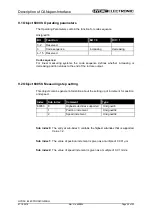
Страница 46: ...und das Kommando Parameter abspeichern nicht ausgeführt worden ist nach dem nächsten Einschalten der Betriebsspannung die Parameter wieder die alten Werte besitzen Bei Schreibzugriff speichert das Gerät die Parameter in den nichtflüchtigen Speicher Dieser Vorgang dauert ca 3s In dieser Zeit ist das Mess System auf dem Bus nicht ansprechbar Um eine versehentliche Speicherung der Parameter zu vermei...

Страница 47: ...dert worden sind und das Kommando Parameter rücksetzen ausgeführt worden ist werden die Parameter wieder die Werte der Werkseinstellung besitzen Bei Schreibzugriff speichert das Gerät die Parameter in den nichtflüchtigen Speicher Dieser Vorgang dauert ca 3s In dieser Zeit ist das Mess System auf dem Bus nicht ansprechbar Um ein versehentliches Rücksetzen der Parameter zu vermeiden wird das Rückset...

Страница 48: ...dor ID des Herstellers Die Vendor ID von HYDAC ELECTRONIC GmbH ist 218 bzw 0xDA Subindex2 Bei Lesezugriff liefert das Gerät Informationen über den Produktcode Mit zugehörigem Geräteprofil Subindex3 Bei Lesezugriff liefert das Gerät Informationen über die Revisionsnummer Subindex4 Bei Lesezugriff liefert das Gerät Informationen über die Seriennummer 8 13 Objekt 1F80 NMT Startup read write Wird Bit ...

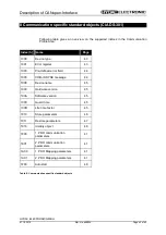
Страница 49: ...zeigt alle vom HLT 1100 unterstützten Einträge Index h Name Seite Parameter 6000 Betriebsparameter 50 6005 Einstellung der Messschritte 50 6010 Presetwert 51 6020 Positionswert 52 6030 Geschwindigkeitswert 52 6200 Cyclic Timer 53 Diagnose 6500 Betriebsstatus 53 6501 Mess Schritt 53 6503 Alarme 54 6504 Unterstützte Alarme 55 6505 Warnungen 55 6506 Unterstützte Warnungen 55 6507 Profil und Softwarev...

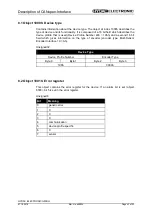
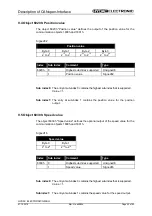
Страница 50: ...s Stabes ausgegeben werden 9 2 Objekt 6005h Einstellung der Messschritte Dieses Objekt enthält generelle Informationen über die eingestellten Schrittweiten für Position und Geschwindigkeit Index Subindex Kommentar Typ 6005h 0 größter unterstützte Subindex Unsigned8 1 Positionsschrittweite Unsigned32 2 Geschwindigkeitsschrittweite Unsigned32 Subindex0 Der Eintrag in Subindex 0 enthält den größten u...

Страница 51: ...ie Presetfunktion wird verwendet um den Mess System Wert auf einen beliebigen Positionswert innerhalb des Bereiches von 0 bis Messlänge in Schritten 1 zu setzen Der Ausgabe Positionswert wird auf den Parameter Presetwert gesetzt wenn auf dieses Objekt geschrieben wird Signed32 Presetwert Byte 0 Byte 1 Byte 2 Byte 3 27 bis 20 215 bis 28 223 bis 216 231 bis 224 Index Subindex Kommentar Typ 6010h 0 g...

Страница 52: ... 0 enthält den größten unterstützten Subindex Wert 1 Subindex1 Der Eintrag in Subindex 1 enthält den Positionswert für die Positionsausgabe 9 5 Objekt 6030h Geschwindigkeitswert Das Objekt 6030h Geschwindigkeitswert definiert den optionalen Geschwindigkeitsausgabewert für die Kommunikationsobjekte 1800h und 1801h Signed16 Geschwindigkeitswert Byte 0 Byte 1 27 bis 20 215 bis 28 Index Subindex Komme...

Страница 53: ... Objekt Objekt 1800h die Mess System Position Dieses Objekt ist identisch mit dem Objekt 1800 Subindex 5 9 7 Objekt 6500h Betriebsstatus Dieses Objekt enthält den Betriebsstatus des Mess Systems und beinhaltet Informationen über die intern programmierten Parameter Unsigned16 Bit Funktion Bit 0 Bit 1 0 2 reserviert 3 Zählrichtung steigend fallend 4 15 reserviert 9 8 Objekt 6501h Mess Schritt linear...

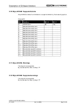
Страница 54: ...gned16 Bit Funktion Bit 0 Bit 1 0 Positionsfehler Nein Ja 1 Reserviert für weitere Verwendung 2 Reserviert für weitere Verwendung 3 Reserviert für weitere Verwendung 4 Reserviert für weitere Verwendung 5 Reserviert für weitere Verwendung 6 Reserviert für weitere Verwendung 7 Reserviert für weitere Verwendung 8 Reserviert für weitere Verwendung 9 Reserviert für weitere Verwendung 10 Reserviert für ...

Страница 55: ...tere Verwendung 5 Reserviert für weitere Verwendung 6 Reserviert für weitere Verwendung 7 Reserviert für weitere Verwendung 8 Reserviert für weitere Verwendung 9 Reserviert für weitere Verwendung 10 Reserviert für weitere Verwendung 11 Reserviert für weitere Verwendung 12 Herstellerspezifische Funktionen 13 Herstellerspezifische Funktionen 14 Herstellerspezifische Funktionen 15 Herstellerspezifisc...

Страница 56: ...n siehe Seite 45 Unsigned32 Profilversion Softwareversion Byte 0 Byte 1 Byte 2 Byte 3 2 7 bis 2 0 2 15 bis 2 8 2 7 bis 2 0 2 15 bis 2 8 9 14 Objekt 6508h Betriebszeit Die Betriebszeit Funktion wird nicht verwendet der Betriebszeitwert wird auf den Maximalwert gesetzt FF FF FF FF h 9 15 Objekt 650Ah Modul Identifizierung Die Sub Indices 1 3 enthalten Informationen über herstellerspezifische Einstel...

Страница 57: ...alt Emergency Fehlercode Objekt 1003h Byte 0 1 Fehler Register Objekt 1001h 0 0 0 0 0 COB Identifier 080h Node ID Wenn das Mess System einen internen Fehler erkennt wird eine Emergency Meldung mit dem Fehlercode des Objekts 1003h Vordefiniertes Fehlerfeld und dem Fehler Register Objekt 1001h übertragen Zusätzlich zum Emergency Objekt wird im Alarm Objekt 6503H das zugehörige Bit gesetzt Wenn der F...

Страница 58: ...ess System den Positionswert einmal mit der COB ID des Objekts 1800h Jetzt kann der Positionswert auf verschiedene Arten übertragen werden 1 Asynchron Übertragung Das erste Sende Prozessdaten Objekt Objekt 1800h überträgt den Positionswert des Mess Systems in Zeitintervallen Der Timerwert wird definiert durch den Wert des Cyclic Timers Objekt 6200h oder 1800 5 Diese Übertragung startet automatisch...

Страница 59: ...derung Remote Sync Das Mess System empfängt ein Remote Frame mit der COB ID Standardwert 280h Node ID Objekt Funktions Code COB ID Index Kommunikations Parameter PDO2 tx 0101bin 281h 2FFh 1801h Das Mess System empfängt ein SYNC Telegramm mit der COB ID Standardwert 080h definiert in Objekt 1005h Alle Slaves mit dieser SYNC COB ID übertragen den Positionswert Objekt Funktions Code COB ID Index Komm...

Страница 60: ...riff auf ein Objekt Überprüfen welches Attribut für das entsprechende Objekt gültig ist rw Lese und Schreibzugriff wo nur Schreibzugriff ro nur Lesezugriff Const nur Lesezugriff 0x0609 0011 Subindex nicht vorhanden Überprüfen welche Subindexe das entsprechende Objekt unterstützt 0x0800 0000 Allgemeiner Fehler Falsche Signatur beim Abspeichern der Parameter geschrieben siehe Objekt 1010h Parameter ...

Страница 61: ...cher Fehler 1 0 2 0 3 0 4 Kommunikation 5 geräteprofilspezifisch 6 0 7 Sensor 12 2 2 Objekt 1003h Vordefiniertes Fehlerfeld Bits 0 15 Über das Emergency Objekt wird immer nur der zuletzt aufgetretene Fehler angezeigt Für jede EMCY Nachricht die gelöscht wurde wird eine Emergency Meldung mit Fehlercode 0x0000 übertragen Das Ergebnis kann dem Objekt 0x1003 entnommen werden Wenn kein Fehler mehr vorl...

Страница 62: ...erter Parameter außerhalb Bereich Min bzw Max Werte der einzelnen Parameter überprüfen 12 4 Sonstige Störungen Störung Ursache Abhilfe starke Vibrationen Vibrationen Schläge und Stöße z B an Pressen werden mit so genannten Schockmodulen gedämpft Wenn der Fehler trotz dieser Maßnahmen wiederholt auftritt muss das Mess System getauscht werden elektrische Störungen EMV Gegen elektrische Störungen hel...

Страница 63: ... Service zur Verfügung HYDAC SERVICE GMBH Hauptstr 27 D 66128 Saarbrücken Germany Tel 49 0 6897 509 1936 Fax 49 0 6897 509 1933 Anmerkung Die Angaben in dieser Bedienungsanleitung beziehen sich auf die beschriebenen Betriebsbedingungen und Einsatzfälle Bei abweichenden Einsatzfällen und oder Betriebsbedingungen wenden Sie sich bitte an die entsprechende Fachabteilung Bei technischen Fragen Hinweis...

Страница 64: ...Translation of original instruction Linear Transducer Serie HLT 1100 with CANopen interface Additional safety instructions Installation Commissioning Configuration Parameterization Cause of faults and remedies Software Support CD Mat No 3505546 ...

Страница 65: ...726 Email electronic hydac com Copyright protection This Manual including the illustrations contained therein is subject to copyright protection Use of this Manual by third parties in contravention of copyright regulations is forbidden Reproduction translation as well as electronic and photographic archiving and modification require the written content of the manufacturer Offenders will be liable ...

Страница 66: ...Node Life guarding services 22 4 7 Layer setting services LSS and protocols 23 4 7 1 LSS Modes and Services 24 4 7 2 Transmission of LSS services 26 4 7 2 1 LSS message format 26 4 7 3 Switch mode protocols 26 4 7 3 1 Switch mode global protocol 26 4 7 3 2 Switch mode selective protocol 27 4 7 4 Configuration protocols 28 4 7 4 1 Configure Node Id address protocol 28 4 7 4 2 Configure bit timing p...

Страница 67: ...dard objects CiA DS 301 42 8 1 Object 1000h Device type 43 8 2 Object 1001h Error register 43 8 3 Object 1003h Pre defined error field 44 8 4 Object 1005h COB ID SYNC message 44 8 5 Object 1008h Device name 45 8 6 Object 1009h Hardware version 45 8 7 Object 100Ah Software version 45 8 8 Object 100Ch Guard time 45 8 9 Object 100Dh Life time factor 45 8 10 Object 1010h Store parameters 46 8 11 Objec...

Страница 68: ... version 56 9 14 Object 6508h Operating time 56 9 15 Object 650Ah Modul identification 56 9 16 Object 650Bh Serial number 56 9 17 Object 650Ch Offsetwert 56 10 Emergency Message 57 11 Transmission of the measuring system position value 58 12 Causes of faults and remedies 60 12 1 SDO Error codes 60 12 2 Emergency Error codes 60 12 2 1 Object 1001h Error register 61 12 2 2 Object 1003h Pre defined E...

Страница 69: ...lementary to other documentation such as product datasheets dimensional drawings leaflets and the assembly instructions etc The User Manual may be included in the customer s specific delivery package or it may be requested separately 1 1 Applicability This User Manual applies exclusively to the following measuring system models with CANopen interface HLT 1100 The products are labeled with affixed ...

Страница 70: ...96 6 CiA DS 202 3 V1 1 CMS Encoding Rules February 1996 7 CiA DS 203 1 V1 1 NMT Service Specification February 1996 8 CiA DS 203 2 V1 1 NMT Protocol Specification February 1996 9 CiA DS 204 1 V1 1 DBT Service Specification February 1996 10 CiA DS 204 2 V1 1 DBT Protocol Specification February 1996 11 CiA DS 205 1 V1 1 LMT Service Specification February 1996 12 CiA DS 205 2 V1 1 LMT Protocol Specif...

Страница 71: ...r in the CAN Reference Model COB Communication Object CAN Message A unit of transportation in a CAN Network Data must be sent across a Network inside a COB COB ID COB Identifier Identifies a COB uniquely in a Network The iden tifier determines the priority of that COB in the MAC sub layer too DBT Distributor One of the service elements of the application in the CAN Reference Model It is the respon...

Страница 72: ...r the product used 2 2 Additional instructions for proper use The measurement system is designed for operation with CANopen networks according to the International Standard ISO DIS 11898 and 11519 1 up to max 1 Mbit s The profile corresponds to the CANopen Device Profile for Encoder CiA DS 406 V2 0A The technical guidelines for the structure of the CANopen network from the CAN User Organization Ci...

Страница 73: ...asurement system Prior to commencing work personnel working with the measurement system must have read and understood the assembly instructions in particular the chapter Basic safety instructions and this User Manual in particular the chapter Additional safety instructions This particularly applies for personnel who are only deployed occasionally e g at the parameterization of the measurement syst...

Страница 74: ... Bit Integer CANopen EN 50325 4 Bus connection ISO 11898 1 ISO 11898 2 CAN Specification 2 0 A 11 Bit Identifier Communication Profile CiA DS 301 V4 2 Device Profile CiA DS 406 V3 2 LSS CiA DS 305 V2 2 Node ID 1 127 Baud rate 20 50 125 250 500 800 1000 kbit s Connection Copper cable 4 x 0 5 mm Special features Programming of the following parameters via the CAN BUS Node adress Baudrate Code sequen...

Страница 75: ...8 2 In the automation technology these are extended by the recommendations of the CiA industry association with regard to the pin assignment and transmission rates In the area of the application layer CiA has developed the standard CAL CAN Application Layer Figure 1 CANopen classified in the ISO OSI reference model In case of CANopen at first the communication profile as well as a Build instructio...

Страница 76: ...exchange Here real time data e g position value and parameter data e g code sequence will be differentiated To the data types which are different from the character CANopen assigns respectively suitable communication elements Figure 2 Communication profile Special Function Object SFO Synchronization SYNC Emergency EMCY Protocol Network Management Object NMO e g Life Node Guarding Boot Up Error Con...

Страница 77: ... Data Object SDO Service Data Objects manage the parameter data exchange such as the non cyclical execution of the Preset function For parameter data of arbitrary size with the SDO an efficient communication mechanism is available For this between the configuration master and the connected devices a service data channel for the parameter communication is available The device parameters can be writ...

Страница 78: ...SDO Figure 4 Structure of the Object Dictionary 4 4 CANopen default identifier CANopen devices can be used without configuration in a CANopen network Just the setting of a bus address and the baud rate is required From this node address the identifier allocation for the communication channels is derived COB Identifier Function Code Node ID 10 0 1 2 3 4 1 2 3 4 5 6 7 Function Code Node ID Examples ...

Страница 79: ...e format The data field with max 8 byte length of a CAN message is used by a SDO as follows CCD Index Sub Index Data Byte 0 Byte 1 Low Byte 2 High Byte 3 Byte 4 Byte 5 Byte 6 Byte 7 Table 2 SDO message The command code CCD identifies whether the SDO is to be read or written In addition with a writing order the number of bytes which can be written is encoded in the CCD At the SDO response the CCD r...

Страница 80: ...f data segments and the number of bytes to be read is reported With following reading requests the individual data segments can be read A data segment consists respectively of 7 bytes Example of reading a data segment Telegram 1 CCD Meaning Valid for 0x40 Reading request initiation SDO Request 0x41 1 data segment available The number of bytes which can be read is indicated in the bytes 4 to 7 SDO ...

Страница 81: ... The Read SDO telegram has to be send to the slave The slave answers with the following telegram Response Protocol format COB Identifier 580h Node ID Read SDO s Byte 0 1 2 3 4 5 6 7 Contents Code Index Sub Index Data 0 Data 1 Data 2 Data 3 4xh Low High Byte Data Data Data Data Format Byte 0 MSB LSB 7 6 5 4 3 2 1 0 0 1 0 0 n 1 1 n number of data bytes bytes 4 7 that does not contain data If only 1 ...

Страница 82: ...0 0 0 0 Format Byte 0 MSB LSB 7 6 5 4 3 2 1 0 0 0 1 0 n 1 1 n number of data bytes bytes 4 7 that does not contain data If only 1 data byte Data 0 contains data the value of byte 0 is 2FH The Write SDO telegram has to be send to the slave The slave answers with the following telegram Response Protocol format COB Identifier 580h Node ID Read SDO s Byte 0 1 2 3 4 5 6 7 Contents Code Index Sub Index ...

Страница 83: ... system is first in the Pre Operational condition 2 Stopped 14 9 2 3 4 7 5 8 6 Power ON or Hardware Reset 13 12 10 11 1 Initialization Pre Operational Operational Figure 5 Boot Up mechanism of the network management State Description 1 At Power on the initialization state is entered autonomously 2 Initialization finished enter PRE OPERATIONAL automatically 3 6 Start_Remote_Node Operational 4 7 Ent...

Страница 84: ...ommands are defined CCD Meaning State At Power on the initialization state is entered autonomously 1 Initialization finished enter PRE OPERATIONAL automatically 2 0x01 Start Remote Node Node is switched into the OPERATIONAL state and the normal net operation is started 3 6 0x02 Stop Remote Node Node is switched into the STOPPED state and the communication is stopped An active connecting monitoring...

Страница 85: ... the Node Guarding Protocol toggles after each request Example 0x85 0x05 0x85 no error 0x85 0x05 0x05 error Additionally if the Life Guarding is active the NMT slave requests the state of a NMT master in regular intervals otherwise the slave changes into the PRE OPERATIONAL state The NMT services for Node Live guarding use the function code 1110 bin COB ID 0x700 Node ID Index Description 0x100C Gu...

Страница 86: ...Serial Number The measuring system supports the following services Switch mode services W Switch mode selective To response a specific of LSS Slave W Switch mode global To response all of LSS Slaves Configuration services W Configure Node ID W Configure bit timing parameters W Activate bit timing parameters W Store configured parameters Inquiry services W Inquire LSS address W Inquire Node ID Iden...

Страница 87: ...FSAs 1 LSS waiting Support for all services as indicated below 2 LSS configuration Support for all services as indicated below 3 Final Pseudo State shows the deactivation of the FSAs Figure 6 LSS Modes State behavior of the supported services Services Waiting Configuration Switch mode global Yes Yes Switch mode selective Yes No Activate bit timing parameters No Yes Configure bit timing parameters ...

Страница 88: ...LSS switch state global command with parameters configuration_switch or switch state selective command no 3 LSS switch state global command with parameter waiting_switch no 4 Automatic transition when an invalid Node ID has been changed and the new Node ID could be successfully stored in nonvolatile memory AND the state of LSS waiting has been requested no Once the LSS FSA further state transition...

Страница 89: ...or LSS services 4 7 2 1 LSS message format The data field with max 8 byte length of a CAN message is used by a LSS service as follows CS Data Byte 0 Byte 1 Byte 2 Byte 3 Byte 4 Byte 5 Byte 6 Byte 7 Table 7 LSS message Byte 0 contains the Command Specifier CS afterwards 7 byte data are following 4 7 3 Switch mode protocols 4 7 3 1 Switch mode global protocol The given protocol has implemented the S...

Страница 90: ...he LSS address LSS Master LSS Slave 0 1 2 3 4 5 6 7 COB ID CS Vendor Id Reserved by CiA 0x7E5 64 LSB MSB 0 1 2 3 4 5 6 7 COB ID CS Product Code Reserved by CiA 0x7E5 65 LSB MSB 0 1 2 3 4 5 6 7 COB ID CS Revision Number Reserved by CiA 0x7E5 66 LSB MSB 0 1 2 3 4 5 6 7 COB ID CS Serial Number Reserved by CiA 0x7E5 67 LSB MSB LSS Slave LSS Master 0 1 2 3 4 5 6 7 COB ID CS Reserved by CiA 0x7E4 68 Err...

Страница 91: ...one device is to be switched into Configuration Mode For storage of the new Node ID the Store configuration protocol must be transmitted to the LSS slave LSS Master LSS Slave 0 1 2 3 4 5 6 7 COB ID CS Node ID Reserved by CiA 0x7E5 17 1 127 and 255 LSS Slave LSS Master 0 1 2 3 4 5 6 7 COB ID CS Error Code Spec Error Reserved by CiA 0x7E4 17 Error Code 0 Protocol successfully completed 1 254 reserve...

Страница 92: ... transmitted to the LSS slave LSS Master LSS Slave 0 1 2 3 4 5 6 7 COB ID CS Table Selector Table Index Reserved by CiA 0x7E5 19 0 0 7 LSS Slave LSS Master 0 1 2 3 4 5 6 7 COB ID CS Error Code Spec Error Reserved by CiA 0x7E4 19 Table Selector 0 Standard CiA Baud rate table Table Index 0 1 Mbit s 1 800 kbit s 2 500 kbit s 3 250 kbit s 4 125 kbit s 5 reserved 6 50 kbit s 7 20 kbit s Error Code 0 Pr...

Страница 93: ...ocessing duration the switching internally in the LSS slave is performed After the time D2 the LSS slave responses with CAN messages and the new configured Baud rate It is necessary Switch Delay longest occurring processing duration of a LSS slave 4 7 4 4 Store configuration protocol The given protocol has implemented the Store configuration service By means of the LSS master the configured parame...

Страница 94: ...LSS Slave 0 1 2 3 4 5 6 7 COB ID CS Reserved by CiA 0x7E5 90 LSS Slave LSS Master 0 1 2 3 4 5 6 7 COB ID CS Vendor Id Index 1018h 01 Reserved by CiA 0x7E4 90 LSB MSB 4 7 5 2 Inquire Identity Product Code protocol The given protocol has implemented the Inquire LSS address service By means of the LSS master the Product Name of a single LSS slave in the network can be read out Only one device is to b...

Страница 95: ...3 4 5 6 7 COB ID CS Reserved by CiA 0x7E5 92 LSS Slave LSS Master 0 1 2 3 4 5 6 7 COB ID CS Revision Number Index 1018h 03 Reserved by CiA 0x7E4 92 LSB MSB 4 7 5 4 Inquire Identity Serial Number protocol The given protocol has implemented the Inquire LSS address service By means of the LSS master the Serial Number of a single LSS slave in the network can be read out Only one device is to be switch...

Страница 96: ...readout in the network This may only find one LSS Slave in configuration mode LSS Master LSS Slave 0 1 2 3 4 5 6 7 COB ID CS Reserved by CiA 0x7E5 94 LSS Slave LSS Master 0 1 2 3 4 5 6 7 COB ID CS Node ID Reserved by CiA 0x7E4 94 1 127 und 255 MSB Node ID Corresponds to the Node ID of the selected device If the Node ID just has been changed about the Configure Node ID service the original Node ID ...

Страница 97: ...r ID Product Code Revision No and Serial No Range response with the LSS identify slave protocol LSS Master LSS Slave 0 1 2 3 4 5 6 7 COB ID CS Vendor Id Reserved by CiA 0x7E5 70 LSB MSB 0 1 2 3 4 5 6 7 COB ID CS Product Code Reserved by CiA 0x7E5 71 LSB MSB 0 1 2 3 4 5 6 7 COB ID CS Revision Number Low Reserved by CiA 0x7E5 72 LSB MSB 0 1 2 3 4 5 6 7 COB ID CS Revision Number High Reserved by CiA ...

Страница 98: ...n the network are identified The related LSS Slaves answer with the LSS identify non configured remote slave protocol LSS Slave LSS Master 0 1 2 3 4 5 6 7 COB ID CS Reserved by CiA 0x7E4 76 4 7 6 4 LSS identify non configured slave Protocol The specified protocol has implemented the LSS identify non configured slave service All LSS Slaves with an invalid Node ID FFh answer with the protocol after ...

Страница 99: ...ice class e g for encoder CiA DS 406 can be responded uniformly On the basis of these standardized profiles CANopen devices can be accessed in an identical way over the bus Therefore devices which support the same device profile are exchangeable with each other You can obtain further information on CANopen from the CAN in Automation User and Manufacturer Association CAN in Automation Am Weichselga...

Страница 100: ... supply voltage can be carried In a CANopen network max 127 slaves can be connected The measuring system supports the Node ID range from 1 127 The transmission rate can be adjusted via LSS Protocol and supports the baud rates 20 kbit s 125 kbit s 500 kbit s and 1 Mbit s The length of a CANopen network is depending on the transmission rate and is represented in the following Cable cross section 20 ...

Страница 101: ...57 In the PRE OPERATIONAL state first only a parameter setting about Service Data Objects is possible But it is possible to configure PDOs with the help of SDOs If the measuring system was transferred into the OPERATIONAL state also a transmission of PDOs is possible 5 3 Setting the Node ID and Baud rate by means of LSS services 5 3 1 Configuration of the Node ID sequence Assumption LSS address un...

Страница 102: ...o switch the LSS slave into Configuration Mode Perform service 19 Configure bit timing parameters protocol Table Selector 0 Table Index 4 Wait for acknowledgement and check successfully execution Error Code 0 Perform service 21 Activate bit timing parameters protocol to switch the new Baud rate active Perform service 23 Store configuration protocol Wait for acknowledgement and check successfully e...

Страница 103: ...sion 3 2 The measuring systems partially support the extended functions in Class C2 The communication functionality and objects which are used in the encoder profile are described in a EDS File Electronic Data Sheet When using a CANopen Configuration Tool e g CANSETTER the user can read the objects of the measuring system SDOs and program the functionality 6 2 EDS file The EDS electronic datasheet...

Страница 104: ...ynchronous way The cyclic timer is stored in Index 1800h Sub 05h and in index 6200h Index Sub Index Comment Default value Attr 1800h 0 number of supported entries 5 ro 1 COB ID used by PDO 1 180h Node ID ro 2 transmission type 254 ro 3 inhibit time 0 rw 5 Event timer 0 rw 1A00h 0 number of mapped objects 1 ro 1 Position value 60200120h ro 7 2 2nd transmit Process Data Object cyclic This PDO transm...

Страница 105: ...001 Error register 43 1003 Pre defined error field 44 1005 COB ID SYNC message 44 1008 Device name 45 1009 Hardware version 45 100A Software version 45 100C Guard time 45 100D Life time factor 45 1010 Store parameters 46 1011 Restore parameters 47 1018 Identity object 48 1800 1 PDO communication parameters 41 1801 2 PDO communication parameters 41 1A00 1 PDO Mapping parameters 41 1A01 2 PDO Mappin...

Страница 106: ...s used Device Profile Number 406 196h and a second 16 bit field which gives information on the type of encoder encoder type Multi Sensor Encoder Interface 10 Ah Unsigned32 Device Type Device Profile Number Encoder Type Byte 0 Byte 1 Byte 2 Byte 3 196h 000Ah 8 2 Object 1001h Error register This object contains the error register for the device If an alarm bit is set object 6503 bit 5 is set in the ...

Страница 107: ...ional error information Unsigned32 Standard Error Field Byte 0 Byte 1 Byte 2 Byte 3 Error code Additional Information 8 4 Object 1005h COB ID SYNC message This object defines the COB ID of the Synchronization Object SYNC Further it defines whether the device consumes the SYNC or whether the device generates the SYNC However the measuring system supports only the processing of SYNC messages and use...

Страница 108: ... manufacturer software version visible string transmission via Segment Protocol 8 8 Object 100Ch Guard time The objects at index 100CH and 100DH include the guard time in milli seconds and the life time factor The life time factor multiplied with the guard time gives the live time for the Node Guarding Protocol Default value 0 Unsigned16 Guard Time Byte 0 Byte 1 2 7 to 2 0 2 15 to 2 8 8 9 Object 1...

Страница 109: ...ters have been changed by the user and no Store Parameter Command had been executed at the next power on the parameters will have there old values In case of write access the device stores the parameters to the non volatile memory This procedure takes approx 3s In this time the measuring system isn t accessible at the bus In order to avoid storage of parameters by mistake storage is only executed ...

Страница 110: ...eters have been changed by the user and Restore Parameter Command had been executed at the next power on the parameters will have the values of factory setting In case of write access the device stores the parameters to the non volatile memory This procedure takes approx 3s In this time the measuring system isn t accessible at the bus In order to avoid restore of parameters by mistake restore is o...

Страница 111: ... Value 4 Sub index1 Contains the Vendor ID of the manufacturer The Vendor ID for HYDAC ELECTRONIC GmbH is 218 0xDA Sub index2 Provides information about the product code with the associated device profile Sub index3 Provides information about the order number Sub index4 Provides information about the serial number 8 13 Objekt 1F80 NMT Startup read write Will be set bit 2 automatically by reaching ...

Страница 112: ...rted by HLT 1100 is shown below Index h Name Page Parameters 6000 Operating parameters 50 6005 Measuring step settings 50 6010 Preset value 51 6020 Position value 52 6030 Speed value 52 6200 Cyclic timer 53 Diagnostics 6500 Operating state 53 6501 Measuring step 53 6503 Alarms 54 6504 Supported alarms 55 6505 Warnings 55 6506 Supported warnings 55 6507 Profile and software version 56 6508 Operatin...

Страница 113: ...g or decreasing position values to the end of the rod are output 9 2 Object 6005h Measuring step setting This object contains generel information about the setting up of increment for position and speed Index Sub index Comment Type 6005h 0 Highest sub index supported Unsigned8 1 Position increment Unsigned32 2 Speed increment Unsigned32 Sub index0 The entry at sub index 0 contains the highest sub ...

Страница 114: ...plication The Preset Function can be used to adjust the measuring system to any position value within a range of 0 to measuring length in increments 1 The output position value is set to the parameter Preset value when writing to this object Signed32 Preset value Byte 0 Byte 1 Byte 2 Byte 3 2 7 to 2 0 2 15 to 2 8 2 23 to 2 16 2 31 to 2 24 Index Sub index Comment Type 6010h 0 Highest sub index supp...

Страница 115: ... The entry at sub index 0 contains the highest sub index that is supported Value 1 Sub index1 The entry at sub index 1 contains the position value for the position output 9 5 Object 6030h Speed value The object 6030h Speed value defines the optional output of the speed value for the communication objects 1800h and 1801h Signed16 Speed value Byte 0 Byte 1 2 7 to 2 0 2 15 to 2 8 Index Sub index Comm...

Страница 116: ... object 1800h transmit the measuring system position 9 7 Object 6500h Operating status This object contains the operating status of the measuring system It gives information on measuring system internal programmed parameters Unsigned16 Bit Function Bit 0 Bit 1 0 2 Reserved 3 Code Sequence increasing decreasing 4 15 Reserved 9 8 Object 6501h Measuring step linear For linear measuring systems object...

Страница 117: ...system is able to provide an accurate position value Unsigned16 Bit Function Bit 0 Bit 1 0 Position error No Yes 1 Reserved for further use 2 Reserved for further use 3 Reserved for further use 4 Reserved for further use 5 Reserved for further use 6 Reserved for further use 7 Reserved for further use 8 Reserved for further use 9 Reserved for further use 10 Reserved for further use 11 Reserved for ...

Страница 118: ...4 Reserved for further use 5 Reserved for further use 6 Reserved for further use 7 Reserved for further use 8 Reserved for further use 9 Reserved for further use 10 Reserved for further use 11 Reserved for further use 12 Manufacturer specific functions 13 Manufacturer specific functions 14 Manufacturer specific functions 15 Manufacturer specific functions 9 11 Object 6505h Warnings This object is ...

Страница 119: ...ct 100Ah see page 45 Unsigned32 Profile version Software version Byte 0 Byte 1 Byte 2 Byte 3 2 7 to 2 0 2 15 to 2 8 2 7 to 2 0 2 15 to 2 8 9 14 Object 6508h Operating time This object is not supported The operating time function is not used the operating time value is set to the maximum value FF FF FF FF h 9 15 Object 650Ah Modul identification The sub indices 1 3 contains information manufacturer...

Страница 120: ...5 6 7 Contents Emergency Error Code Object 1003h Byte 0 1 Error Register Object 1001h 0 0 0 0 0 COB Identifier 080h Node ID If the measuring system detects an internal error an emergency message will be transmitted with the error code of object 1003h pre defined error field and the error register object 1001h Additionally to the emergency object the according bit in the Alarm object 6503h is set I...

Страница 121: ...mit the position value one time with the COB ID of object 1800h Now the measuring system position value can be transmitted in different ways 1 Asynchronous Transmission The 1st transmit PDO object 1800h transmit the position value of the measuring system in time intervals The cyclic time is defined by the value of the cyclic timer object 6200h or 1800 5 This transmission starts automatically after...

Страница 122: ...nt triggering The measuring system receives a remote frame with the COB ID default value 280h Node ID Object Function Code COB ID Index Communication Parameter PDO2 tx 0101bin 281h 2FFh 1801h The measuring system receives a sync telegram with the COB ID default value 080h defined in object 1005h All slaves with this SYNC COB ID will transmit the position value Object Function Code COB ID Index Com...

Страница 123: ...ported access to an object Check which attribute for the corresponding object is valid rw read and write access wo write only access ro read only access Const read only access 0x0609 0011 Sub index does not exist Check which sub indices the corresponding object supports 0x0800 0000 General error Wrong signature written when storing the parameters see Object 1010h Store parameters page 46 Table 10 ...

Страница 124: ...eneric error 1 0 2 0 3 0 4 communication 5 device profile specific 6 0 7 sensor 12 2 2 Object 1003h Pre defined Error field bits 0 15 About the Emergency object only the error occurred last is indicated For each EMCY message which could be deleted an EMCY report with error code 0x0000 is transmitted The result can be taken from object 0x1003 If no more error is present the error register indicates...

Страница 125: ...ed Bit 13 1 Parameter error Programmed parameter out of range Check min and max values of each parameter 12 4 Other faults Fault Cause Remedy Strong vibrations Vibrations impacts and shocks e g on presses are dampened with shock modules If the error recurs despite these measures the measuring system must be replaced Electrical faults EMC Perhaps isolated flanges and couplings made of plastic help ...

Страница 126: ...ns please contact HYDAC Service HYDAC SERVICE GMBH Hauptstr 27 D 66128 Saarbrücken Germany Tel 49 0 6897 509 1936 Fax 49 0 6897 509 1933 Note The information in this manual relates to the operating conditions and applications described For applications and operating conditions not described please contact the relevant technical department If you have any questions suggestions or encounter any prob...

Отзывы: