


5
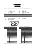
8. HDMI Connector Pin Assignment
Pin#
Function Assignment
Pin#
Function Assignment
1
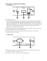
TMDS Data2+
2
TMDS Data2 Shield
3
TMDS Data2-
4
TMDS Data1+
5
TMDS Data1 Shield
6
TMDS Data1-
7
TMDS Data0+
8
TMDS Data0 Shield
9
TMDS Data0-
10
TMDS Clock+
11
TMDS Clock Shield
12
TMDS Clock-
13
CEC
14
Reserved (N.C. on device)
15
SCL
16
SDA
17
DDC/CEC Ground
18
+5V Power
19
Hot Plug Detect
Output Format
1
6
7
11
12
13
14
15
2
3
4
5
10
98
B. Analog VGA output pin assign ment
when output switch set to RGB.
C. Analog VGA output pin assignment
when output switch set to YPbPr.
Part No.
Pin No.
Description (PC out)
Part No.
Pin No.
Description (HD out)
DB15HD
1
RED
DB15HD
1
Pr
2
GREN
2
Y
3
BLUE
3
Pb
4
NC
4
NC
5
GND (DDC-RETURN)
5
GND (DDC-RETURN)
6
GND-RED
6
GND-Pr
7
GND-GREEN
7
GND-Y
8
GND-BLUE
8
GND-Pb
9
N.C
9
N.C
10
GND-SYNC
10
GND-SYNC
11
NC
11
NC
12
DDC-DATA
12
DDC-DATA
13
H-SYNC
13
H-SYNC
14
V-SYNC
14
V-SYNC
15
DDC-CLOCK
15
DDC-CLOCK


