HY-LINE CM-1391M Скачать руководство пользователя страница 9

5

10. DVI-I Pin Configuration

1

8 C1 C2

C5

C4

C3

9

17

24

Combined Analog and Digital Connector Pin Assignments

Pin   Signal Assignment

Pin   Signal Assignment

1
2
3
4
5
6
7
8

C1
C4

T.M.D.S Data2-
T.M.D.S. Data2+
T.M.D.S. Data2 Shield
N.C.
N.C.
DDC Clock
DDC Data
Analog Vertical Sync
Analog Red
Analog Horizontal Sync

9

10
11
12
13
14
15
16

C2
C5

T.M.D.S Data1-
T.M.D.S. Data1+
T.M.D.S. Data1 Shield
N.C.
N.C.
+5V Power
Ground 

(Return for +5V, Hsync, and Vsync)

Hot Plug Detect
Analog Green
Analog Ground

(Analog R,G,&B return)

Pin   Signal Assignment

17
18
19
20
21
22
23
24

C3

T.M.D.S Data0-
T.M.D.S. Data0+
T.M.D.S. Data0 Shield
N.C.
N.C.
T.M.D.S. Clock Shield
T.M.D.S. Clock+
T.M.D.S. Clock-
Analog Blue

DVI-Integrated(DVI-I): Supports both analog and digital connections to the display.

This 29-pin connector can carry single or dual-link all-digital video/data signals 

on 24 pins and uses 5 pins to carry analog video/data signals and ground.

Vertical rate

Resolution

VGA

SVGA

XGA

WXGA

SXGA

UXGA

WUXGA

480p

576p

720p

1080i

1080p

640x480

800x600

1024x768

1280x768

1280x1024

1600x1200

1920x1200

720x480

720x576

1280x720

1920x1080i

1920x1080p

60Hz

60Hz

60Hz

60Hz

60Hz

60Hz

60Hz

60Hz

50Hz

follow input source and can convert 50Hz to 60Hz

follow input source and can convert 50Hz to 60Hz

follow input source and can convert 50Hz to 60Hz
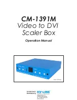
Содержание CM-1391M

Страница 1: ...CM 1391M Video to DVI Scaler Box Operation Manual CM 1391M ...

Страница 2: ...ed in this document Cypress Technology reserves the right to make improvements to this document and or product at any time and without notice No part of this document may be reproduced transmitted tran scribed stored in a retrieval system or any of its part translated into any language or computer file in any form or by any means electronic mechanical magnetic optical chemical manual or otherwise ...

Страница 3: ...shock and injury to persons To prevent fire or shock hazard do not expose the unit to rain moisture or install this product near water Never spill liquid of any kind on or into this product Never push an object of any kind into this product through module openings or empty slots as you may damage parts Do not attach the power supply cabling to building surfaces Do not allow anything to rest on the...

Страница 4: ...lication 1 3 Package Contents 1 4 System Requirements 1 5 Features 1 6 Specifications 2 7 Operation Controls and Functions 2 8 Output Format 3 9 OSD Operation 4 10 DVI I Pin Configuration 5 11 Remote Control 5 12 Connection and Installation 6 ...

Страница 5: ...enu for picture quality adjustment 8 Front Panel and IR remote control 9 Automatic NTSC PAL video format detection 2 Application Digital Analog composite signal display on DVI monitor Digital Analog S Video signal display on DVI monitor NTSC PAL signal display on DVI monitor DVD VCR signal display on DVI monitor 4 System Requirements Input source equipment such as Set Top Box or DVD player and out...

Страница 6: ... Video to DVI Scaler Box CV SV 1 2 3 4 5 6 Input Signal Levels Video 1Vp p 75 ohm Y 1 Vp p 75 ohm Color 0 7 Vp p 75 ohm Digital RGB Output Connector Output Signal Bit stream Weight g 400 125 W x 123 D x 30 H 0 C 40 C Process Blue 4 5W Dimensions mm Output Format DVI I Connector Operating Temperature Silkscreen Color Power Consumption HDTV RGBHV HDTV RGBHV PC RGBHV PC RGBHV VGA 640 x 480 60Hz 1080p...

Страница 7: ...V input of the scaler 3 S Video Use a S Video cable to connect the S Video output of the source video equipment to this S Video input on the back of the video scaler S Video provides improved performance over composite video and is recommended over composite 4 DVI output The Video to DVI Scaler Box can output a variety of PC and HDTV progressive resolutions in both digital and analog format throug...

Страница 8: ... as below comes up Bright Contrast Color Tint Sharp Default Exit USE to move the tick V to your desired adjust item Press the Menu Enter to confirm your selection At this point the selected parameter will turn red and you can use to increase or decrease the value of the parameter When adjustment is complete Press Menu to leave the parameter Move the tick V to Exit then press menu enter to exit 9 O...

Страница 9: ...4 C3 T M D S Data0 T M D S Data0 T M D S Data0 Shield N C N C T M D S Clock Shield T M D S Clock T M D S Clock Analog Blue DVI Integrated DVI I Supports both analog and digital connections to the display This 29 pin connector can carry single or dual link all digital video data signals on 24 pins and uses 5 pins to carry analog video data signals and ground Vertical rate Resolution VGA SVGA XGA WX...

Страница 10: ...t resolution on the screen 2 Power Power ON OFF button 3 VGA 1080p Press to select your desired output resolution 4 Picture Press the button to enter picture adjust submenu Use button to move cursor V up down to your desired parameter press Picture again to confirm 5 Press to move up down the cursor V to your desired parameter or press to increase decrease the setting value 6 Reset Press to reset ...

Страница 11: ...Acronyms A Acronym Complete Term CV Composite Video NTSC National Television System Committee OSD On Screen Display PAL Phase Alternating Line RGB Red Green Blue SV S Video ...

Страница 12: ...20101105 MPM CM1391M Home page http www cypress com tw CYPRESS TECHNOLOGY CO LTD ...

Отзывы: