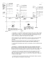
( ) Assemble 1
1/4
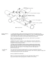
" compression clamp and slip it onto the R-1 section. Refer to Figure
5. Select the R-2 section
(
1
1/8"
x 55"). Slip the unswaged (untapered) end of the R-2
section into the R-1 section and measure the dimension shown on Figure 3 for your
mode of transmission. Tighten the compression clamp slightly.
NOTE: Decide which mode of transmission you will use. Figure 3 shows dimensions
for CW and Phone, but you must use only one mode throughout the antenna
assembly.
If you tried to use the Low Phone dimension on one band and the Medium Phone
dimension on another band, the antenna wouldn't give optimum performance.
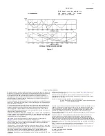
To decide which transmiting mode is best for your purposes, refer to the VSWR charts
in Figure 7.
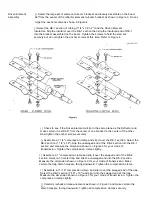
( ) Assemble a 1 " compression clamp and slip it onto the unswaged end of the R-2
section. Select the 10-meter trap and slip the unswaged end into the R-2 section.
Measure the dimension shown on Figure 3 for your mode of transmission. Make certain
the trap drain holes are
.
facing downward. Tighten the compression clamp slightly. .
( ) Assemble 11/16" compression clamp and slip it over the swaged end of the 10-
meter trap. Select the R-3 section (7/16" x 19")
and slip it into the 10-meter trap.
Measure the dimension shown in Figure 3 for your mode of transmission. Tighten the
compression clamp slightly.
( ) Carefully recheck all measurements and be sure the trap drain holes are pointed
down. Now tighten all compression clamps securely.


