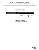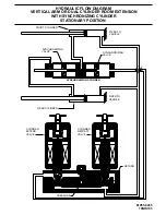
"LEVEL-OUT" (ANGLE MOUNT) ROOM EXTENSION MECHANISM
MANUAL ROOM RETRACTION PROCEDURES
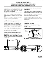
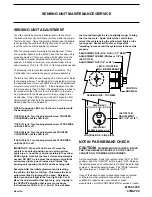
Manual Retraction Bolt
Thumb Screw
5. Replace both Thumb Screws.
MP35.953C
01JUN07
OPERATING PROCEDURES
DO NOT over tighten.
IMPORTANT: If at any stage something is not
understood or if the room begins to bind DO NOT force
the room, contact HWH Customer Service for assistance
1-800-321-3494.
8. Replace both Thumb Screws. Leave the manual valve
releases open.
7. Repeat steps 4 and 5 alternating from mechanism to
mechanism rotating each Manual Retraction Bolt 12
FT.LBS. FORCING THE MANUAL RETRACT BOLT MAY
6. Return to the first room extension mechanism and rotate
the Manual Retraction Bolt clockwise 12 complete turns.
5. Move to the second room extension mechanism, rotate
the Manual Retraction Bolt clockwise 12 complete turns.
4. Using wrench provided, a personal wrench or a tire iron
with a 13/16" or 21mm opening rotate either mechanism’s
Manual Retraction Bolt clockwise 6 complete turns.
3. Remove the Thumb Screws (one on each mechanism)
completely by turning them counterclockwise.
2. Gain access to the 13/16" Manual Retraction Bolts (one
on each mechanism) by raising the STORE-MORE access
panel.
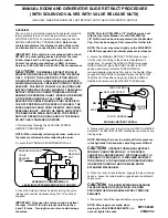
1. Determine which extend and retract solenoid valves are
assigned to the room. Manually open the valve release nuts
for the extend and retract solenoid valves by turning the 1/4"
release nuts counter clockwise 4 and 1/2 turns. Turning the
6. Close both manual valve releases assigned to the
room. Turn the valve release nuts clockwise until snug.
4. Move to the second room extension mechanism and
repeat step 3.
3. If needed, using wrench provided, a personal wrench or
a tire iron with a 13/16" or 21mm opening rotate either
mechanism’s Manual Retraction Bolt counterclockwise until
resistance is met.
2. Remove the Thumb Screws (one on each mechanism)
completely by turning them counterclockwise.
1. Gain access to the 13/16" Manual Retraction Bolts (one
on each mechanism) by raising the STORE-MORE access
panel.
IMPORTANT: DO NOT EXTEND THE ROOM
UNTIL THE STEPS BELOW HAVE BEEN
COMPLETED!
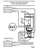
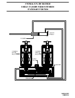
SOLENOID VALVES
LEVELING SYSTEM MANIFOLD NOT SHOWN
HYDRAULIC PUMP/MANIFOLD
nuts more could damage the valves.
NOTE: The breather cap dip stick is also a 1/4" nut driver.
VALVE
RELEASE
NUT
VALVE
RELEASE
NUT
BREATHER
CAP-DIP
STICK
Actual Mounting May Differ
valves on the pump/manifold arrangement. There are 4
valves for the leveling system (if applicable) and 2 valves
If necessary, open all
for each HWH room extension.
complete turns until room is sealed.
EXCEED 15
Make
sure the room does not bind.
(2 FOR EACH ROOM)
(DO NOT
DAMAGE THE MANUAL RETRACT MECHANISM.)
THOROUGHLY
IMPORTANT: READ THESE INSTRUCTIONS
THE MANUAL RETRACT BOLTS TO RETRACT
BEFORE ATTEMPTING TO USE
THE ROOM.

