11
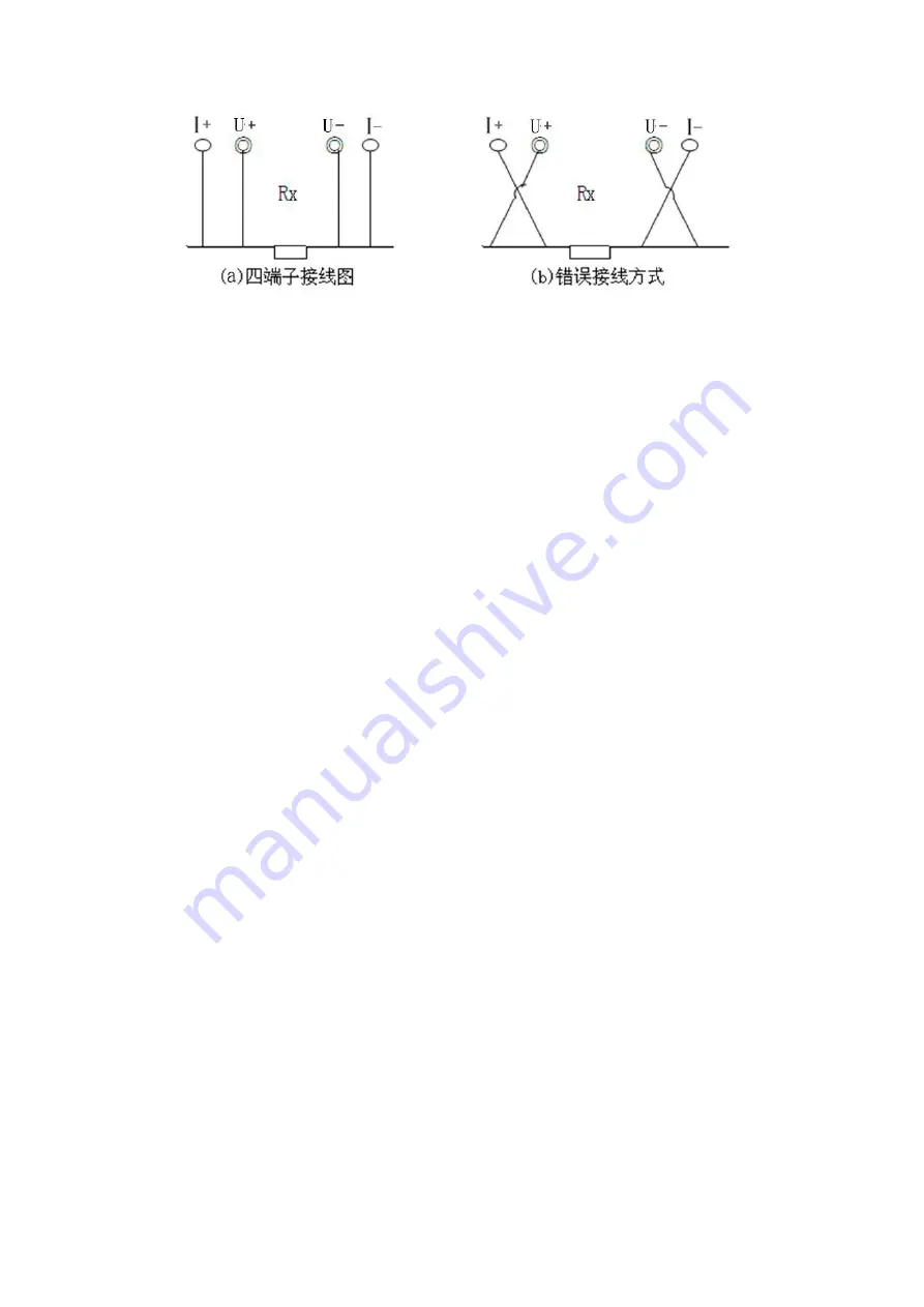
4 terminal wiring diagram
Wrong wiring method
Fig. 3 and 4 terminal wiring diagram
2. The connection between the instrument panel and the test line
should be tight and there should be no looseness.
3. It should be wired according to the four-terminal method, that is,
the current line should be clamped on the outside of the test object,
and the voltage line should be clamped inside the test object. The
current and voltage must be the same polarity.
4. After checking and confirming the error, connect 220V AC, close
the power switch, and the instrument enters the power-on state.
5. Adjust the “Current Selection” knob to select the current gear to
be selected, and then press the “Measure” button. The resistance
meter display value is the measured loop resistance value. If 1 is
displayed, it indicates that the measured loop resistance value is
out of range.


