background image

HVFL Unvented Gas Logs

59D1016

9

OPERATING INSTRUCTIONS and CLEANING & SERVICING

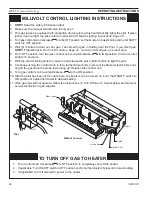
MATCH LIGHTING INSTRUCTIONS

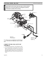
1.  Remove any items necessary for easy access to the pilot (for example: logs, screens, etc.).
.  Follow appropriate lighting instructions found previously. Instead of pushing and releasing the piezo 

button, light a match and hold the flame to the end of the pilot and ignite the pilot.

3.  After control knob has been released and pilot stays lit, reinstall any items that were removed for pilot 

access.

4.  Call a qualified service technician for repair or replacement of the piezo ignitor.

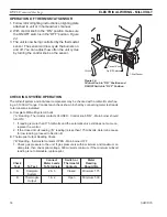
CLEANING AND SERVICING

Annual inspection and cleaning by your dealer or qualified service technician is recommended 
to prevent malfunction and/or sooting.

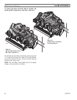
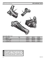
Remove logs, handling carefully by holding gently at each end. Gloves are recommended to prevent 
skin irritation from ceramic fibers. If skin becomes irritated, wash gently with soap and water. Refer 
to manual for correct log placement.

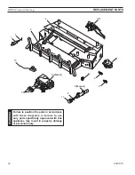
PERIODIC CLEANING - Refer to parts diagram for location of items discussed below.

  Do not use cleaning fluid to clean logs or any part of heater.

• 

Brush logs with soft bristle brush or vacuum with brush attachment.

• 

Vacuum loose particles and dust from the front and rear burner, control and piezo covers and 
grate weldment.

• 

Inspect and clean burner air intake holes. Remove lint or particles with vacuum, brush, or 
pipe cleaners.  

Failure to keep air intake holes clean will result in sooting and poor combustion.

• 

External case should be dusted and wiped with a wet soapy cloth.

ANNUAL CLEANING/INSPECTION - Refer to parts diagram for location of items discussed 
below.

• 

Inspect and clean burner air intake holes. Remove lint or particles with vacuum, brush or 
pipe cleaners.  

Failure to keep air intake holes clean will result in sooting and poor combustion.

• 

Inspect and clean all burner ports.

• 

Inspect ODS pilot for operation and accumulation of lint at air intake holes.

• 

Verify flame pattern and log placement for proper operation.

• 

Verify smooth and responsive ignition of main burner and rear burner.

• 

Replace battery in remote control device. 

W

ARNING

Turn  off  heater  and  allow  to  cool  before 
cleaning.  Disconnect  electrical  power 
before cleaning or servicing.

Содержание 18HVFL

Страница 1: ...neighbor s phone Follow the gas supplier s instructions If you cannot reach your gas supplier call the fire department Installation and service must be performed by a qualified installer service agen...

Страница 2: ...E USING THE APPLIANCE IMPORTANT Read all instructions and warnings carefully before starting installation Failure to follow these instructions may result in a possible fire hazard and will void the wa...

Страница 3: ...area of firebox Ceiling fans may create drafts that alter burner flame patterns Sooting and improper burning will occur 14 Caution Candles incense oil lamps etc produce combustion byproducts includin...

Страница 4: ...er Immediately call a qualified service technician to inspect the room heater and to replace any part of the control system and any gas control which has been under water 24 This appliance must not be...

Страница 5: ...um of 13 0 w c for LP systems ignition controls Piezo ignitor allows ignition of the pilot without the use of matches or batteries Manual control has three 3 positions OFF All gas to the gas logs is s...

Страница 6: ...t sensor Carefully inspect the contents for shipping damage If any parts are missing or damaged immediately inform the dealer from whom you purchased the appliance Do not attempt to install any part o...

Страница 7: ...ealed b weather striping has been added on openable windows and doors and c caulking or sealants are applied to areas such as joints around window and door frames between sole plates and floors betwee...

Страница 8: ...cs of the fireplace which in turn can cause the unit to overheat and malfunction WARNING Important information for the installation of this gas log set The following are guidelines for placing a gas l...

Страница 9: ...logs into a fireplace with no wooden mantel shelf or other combustible projection above the fireplace opening measure the heat resistant material height per Figure 5 then see TABLE A Heat resistant ma...

Страница 10: ...ast 12 and observe material to at least 12 profiles shown on Page 15 and observe profiles Fig 7 shown on Page 16 Fig 9 Less than 8 Extend heat resistant mat l Extend heat resistant to at least 8 insta...

Страница 11: ...mum acceptable distance of 6 If your mantel profile is unsafe you may either Raise the mantel to an acceptable height or Remove the mantel 1 6 Minimum FP2801 combustible floor Heater in Fireplace or F...

Страница 12: ...sote or other obstructions Have this cleaning performed annually after installation Seal any fresh air vents or ash clean out doors located on floor or wall of fireplace If not drafting may cause pilo...

Страница 13: ...used per National Fuel Code section 2 6 3 providing gas meets hydrogen sulfide limits and where permitted by local codes Gas piping system must be sized to provide minimum inlet pressure Listed on Dat...

Страница 14: ...ulator is preset and locked to dis courage tampering If the pressure is not as specified replace the regulator with the correct part from the parts list in this manual Remove 1 8 NPT plug located on s...

Страница 15: ...s can cause improper and dangerous operation Verify proper operation after servicing WARNING The milli volt valve is a self powered combination gas control that does not require 110 Vac to oper ate Co...

Страница 16: ...ry life You can protect the receiver and extend battery life by mounting the receiver in a wall or other location outside the fireplace FP2813 remote receiver Remote Wire Con nectors Remote Receiver F...

Страница 17: ...two 2 0 250 male spade terminals for remote or t stat option Figures 22 and 23 7 Install knob to shaft of t stat sensor Figure 22 8 Place thermo bulb in front of the firebox for incoming air HIGH LOW...

Страница 18: ...millivolt meter hav ing a 1 1000 mV range Conduct each check shown in chart by connecting meter test leads to terminals as indicated A Complete Millivolt System Check A Reading Thermostat contacts CLO...

Страница 19: ...these logs with your bare hands Always wear gloves to prevent skin irritation from ceramic fibers After handling the logs wash your hands gently with soap and water to remove any traces of fibers Pla...

Страница 20: ...Cluster 3 Pins LG956 LG957 HVFL SH top center log Top Center Log 4 LG957 Figure 29 2 Place left log cluster 2 on pin located near left edge of base Figure 27 3 Place right log cluster 3 on two pins l...

Страница 21: ...stability Figure 30 2 Place right bottom log 2 on two 2 pins located on right side of base Figure 31 LG958 HVFL SP back log Rear Log 1 Pins LG958 Figure 30 LG959 HVFL SP right bottom log Right Bottom...

Страница 22: ...g 6 LG962 Figure 34 4 Rest back end of top middle log 4 on rear log and place front end of top middle log 4 on bottom right and left logs Figure 33 5 Place top right back log 5 on right bottom log and...

Страница 23: ...e present when the heater is in operation It should just touch the top of the thermocouple tip for natural Refer to Figure 35 for correct pilot flame If the pilot flame does not touch the thermocouple...

Страница 24: ...Figure 37 Seasoned Hardwood Correct Rear Flame Appearance Figure 38 Stacked Pine Correct Rear Flame Appearance LG963 LG964 The left and right rear flames should be yellow and extend 1 2 above the mid...

Страница 25: ...e chemicals are not harmful but may produce annoy ing smoke and smells as they are burned off during the initial operation of the appliance possibly causing headaches or eye or lung irritation This is...

Страница 26: ...tions If you cannot reach your gas supplier call the fire department C Use only your hand to push in or turn the gas control knob Never use tools If the knob will not push in or turn by hand don t tr...

Страница 27: ...release the piezo ignitor button to light the ODS pilot The pilot is located on the left side of the heater behind the middle log and in front of the back log If piezo ignitor does not light the pilo...

Страница 28: ...gas control knob counterclockwise to IGN position Push in control knob for 5 seconds 7 With the control knob pushed in push in and release the piezo ignitor button to light the pilot 8 Continue pushin...

Страница 29: ...diagram for location of items discussed below Do not use cleaning fluid to clean logs or any part of heater Brush logs with soft bristle brush or vacuum with brush attachment Vacuum loose particles a...

Страница 30: ...utoff valve closed 2 Control knob not in PILOT position 3 Control knob not pressed in while in PILOT position 4 Air in gas lines when installed 5 ODS pilot is clogged 6 Gas regulator setting is not co...

Страница 31: ...clogged or dam aged 2 Burner is damaged 3 Gas regulator is defective 1 Vapors from paint or curing process of logs 1 Turning control knob to HIGH posi tion when burner is cold 2 Air in gas line 3 Dir...

Страница 32: ...2 5 Manual 6 10 11 11 3 4 13 9 5 Millivolt 12 591015 HVFL parts WARNING Failure to position the parts in accordance with these diagrams or failure to use only parts specifically approved with this ap...

Страница 33: ...11 Control Knob 1 18D0603 18D0603 18D0603 18D0603 Millivolt Control 5 Control Valve 1 14D0467 14D0468 14D0467 14D0468 8 Front Burner Injector 1 59D2008 59D2010 59D2012 59D2014 9 Rear Burner Injector...

Страница 34: ...or failure to use only parts specifically approved with this appliance may result in property damage or personal injury Seasoned Hardwood Logs Ref Description Qty 18HSHCL 24SHCL 30SHCL 1 Back Log 1 5...

Страница 35: ...Qty 18SPRL 24SPRL 30SPRL 1 Back Log 1 59D1300 59D1307 59D1314 2 Right Bottom Log 1 59D1301 59D1308 59D1315 3 Left Bottom Log 1 59D1302 59D1309 59D1316 4 Top Middle Log 1 59D1305 59D1312 59D1319 5 Top...

Страница 36: ...HVFL Unvented Gas Logs 36 59D1016...

Страница 37: ...HVFL Unvented Gas Logs 59D1016 37...

Страница 38: ...ith the above requirements provided however that during said thirty 30 day period a battery operated carbon monoxide detector with an alarm shall be installed Massachusetts Residents Only Please read...

Страница 39: ...nty will also be void if the appliance is not operated and maintained according to the operating instructions supplied with the appliance and does not extend to 1 firebox burner assembly damage by acc...

Страница 40: ...MHSC 149 Cleveland Drive Paris Kentucky 40361 www mhsc com...

Отзывы: