


PWW
Data Sheet
HUSSMANN CORPORATION, Bridgeton, MO 63044-2483 U.S.A.
2 of 4
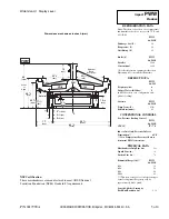
Front
Waste Outlet
& Water Seal
A
Base Rail
Refrigeration
Outlet
Access Area
PWW-8
C
L
(See Note*
)
5
7
/
8
(149)
3
1
/
2
(89)
17
(432)
69
1
/
2
(1765)
86
1
/
2
(2197)
C
B
G
D
E
(See Note***)
(See Note**)
F
Engineering
Plan Views
86 Inch
Wide Island
Bulk Produce
07-2003
Dimensions are shown as inches & (mm).
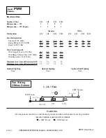
General
4 Ft
6 Ft
8 Ft
12 Ft
(A)
Case length
48
1
/
4
(1226)
72
1
/
4
(1835)
96
3
/
8
(2448) 144
1
/
2
(3670)
Maximum outside dimension of case back to front
86
1
/
2
(2197)
86
1
/
2
(2197)
86
1
/
2
(2197)
86
1
/
2
(2197)
(includes bumper)
Front of splashguard to outside edge of base rail
5
7
/
8
(149)
5
7
/
8
(149)
5
7
/
8
(149)
5
7
/
8
(149)
Back of case to outside edge of front base rail
69
1
/
2
(1765)
69
1
/
2
(1765)
69
1
/
2
(1765)
69
1
/
2
(1765)
Front of case to outside ede of front base rail
17 (432)
17 (432)
17 (432)
17 (432)
Width of base rail
2
1
/
8
(54)
2
1
/
8
(54)
2
1
/
8
(54)
2
1
/
8
(54)
Stub up area between front base rail and splashguard
4
7
/
8
(124)
4
7
/
8
(124)
4
7
/
8
(124)
4
7
/
8
(124)
Electrical Service
(B)
Righthand end of case to center of farthest knockout
47
1
/
4
(1202)
71
1
/
4
(1810)
95
3
/
8
(2423) 143
5
/
8
(3650)
Length of electrical raceway
11
7
/
8
(303)
34
5
/
8
(878)
34
5
/
8
(878)
34
5
/
8
(878)
*Note:
Electrical field wiring connection point.
Waste Outlet
(C)
Right end of case to center of waste outlet
24
1
/
8
(613)
46
5
/
8
(1184)
72
1
/
4
(1835)
72
1
/
4
(1835)
Water Seal
Edge of water seal to center of waste outlet
4 (102)
4 (102)
4 (102)
4 (102)
Center of waste outlet to outside edge of front base rail
3
1
/
2
(89)
3
1
/
2
(89)
3
1
/
2
(89)
3
1
/
2
(89)
** Note:
Field installed water seal outlets, tees, and connectors are shipped with case
Drip Pipe Outlet
(D)
Left end of case to center of drip pipe outlet
20
3
/
8
(517)
19
1
/
2
(495)
19
1
/
2
(495)
68
1
/
2
(1740)
(E)
Center of waste outlet to center of drip pipe outlet
3
3
/
4
(95)
24
3
/
4
(629)
51
7
/
8
(1318)
3
3
/
4
(95)
(F)
Front of case to center of drip pipe outlet
24
7
/
8
(632)
25
7
/
8
(657)
25
7
/
8
(657)
24
7
/
8
(632)
Outside diameter of drip pipe lines
1
1
/
2
(38)
1
1
/
2
(38)
1
1
/
2
(38)
1
1
/
2
(38)
***Note:
Field drip pipe connection point.
Refrigeration Outlet
(D)
Right end of case to center of refrigeration outlet
9 (230)
9 (230)
9 (230)
9 (230)
Center of refrigeration outlet to outside edge
of front base rail
3
1
/
2
(89)
3
1
/
2
(89)
3
1
/
2
(89)
3
1
/
2
(89)


