
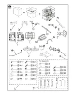


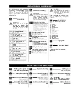


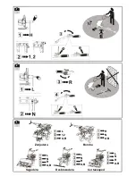

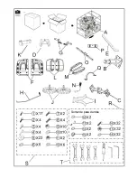
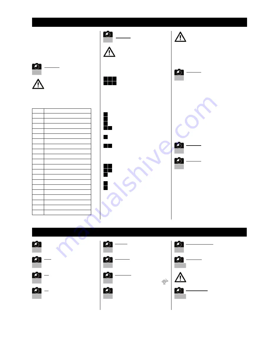
UNPACKING/ ASSEMBLY
Note: In the constant desire to improve
the products, the manufacturer states
that the whole of this manual is not
contractual and reserves the right to
modify th especifications of the machines
without notice.
WARNING:
Take care not to cut the
cables or scratch the
machine’s paintwork when
cutting the edges of the
case.
Ref. Contents of the case
A
Engine Parts
B
Sub Holder 1st
C
Holder Main Comp
D
Lower Tidy Cover
E
Drag Bar
F
Tine Cover
G
Tine Cover Bracket FR.
H
Lever Shifting
I
Blades
J
Wheel
K
Connection Joint
L
Extinsion Cover
M
Side Cover
N
Locking Handle
O
Tine Cover Bracket RR.
P
Rubber Cable Holder
Q
Connecting Plate
R
Hardware Bag Tines only
S
Hardware Bag
T
Tool Bag
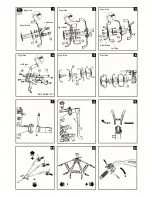
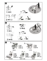
WARNING:
Inappropriate assembly of
this rotary tiller could
cause severe injuries.
Ensure that you follow all
the instructions carefully.
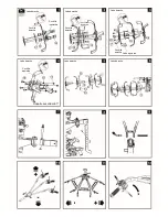
1 2 3
Fitting the tine blades.
4 5 6
Illustrations only shows assembly
of the tin blades on the right side.
Make sure that sharp edges face
one side on both Right and Left
side tines.
Note: Please pay attention to
distinguish the Sub Holder 1st
and Sub Holder 2nd.
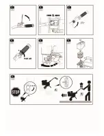
7
Fitting the connecting joint.
8
Fitting the drag bar.
9
Fitting the handle bar.
10 11
Adjusting the position of the
handle bar.
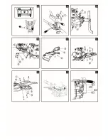
12
Fitting the clutch control.
Turn to proper side and fasten the bolt.
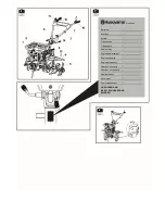
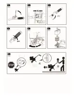
13 14
Fitting the lower tidy cover.
1. Tidy the cables,
2. Put on the rubber holder properly,
3. Put on the cover, and fasten with
bolt.
15 16
Fitting the tine cover.
17 18
Do not tighten the bolt immediately
after installed. Install all 4 bolts and
nuts first, then tighten one by one.
19
20
Fitting the shifting lever.
21
PTO assemble for accessories.
WARNING:
After assembling the machine
completely, tighten all the bolts
and screws with the moderation:
do not overtighten.
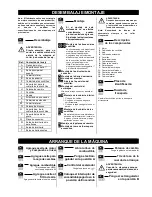
Note: Any dismantling operation must
only be performed by a Husqvarna
workshop.
1
-
Engine
2
-
Tine cover
3
-
Handle
4
-
Extension cover
5
-
Blades
6
-
Drag bar
7
-
Upper tidy cover
8
-
Lever shifting
9
-
Bumper
1
-
Clutch control
11
-
Throttle control
12
-
Reverse control
13
-
Side cover
14
-
Lower tidy cover
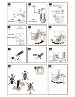
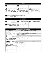
Change the blades with wheels when
transporting
STARTING THE MACHINE
WARNING:
When the machine starts,
remain within the safety zone.
1• 1
Unpacking
1•
2
Assembling
1•
3
Description
of the components
1•
4
Type plate
1•
3
Transport wheel
2
•
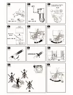
1
Filling with engine oil
and checking the level
2
•
2
Filling with gearbox
oil
2
•
3
Topping up the petrol
Recommend to USE
Octane Value over 90
2
•
4
Add oil to the air filter
Filling the oil to Oil Level
2
•
5
Open the fuel tap
2
•
5
Set the choke in
position A
2
•
6
Throttle control
Put the lever to:
2
•
6
Set the on/off switch to
ON
2
•
5
Shifting lever
Put the lever to gear
N
.
2
•
10
Pull the recoil start
handle
2
•
11
Set the choke in
position B
Содержание TF545P
Страница 2: ...For tines only ...
Страница 4: ......
Страница 7: ...L 1 2 A B H N A B L N R A B L N R A B L N R A B Mower Grass cutter Swather Pump Ditcher ...
Страница 8: ...OFF OFF ...
Страница 14: ...Sólo para fresas ...
Страница 16: ......
Страница 19: ...L 1 2 A B H N A B L N R A B L N R A B L N R A B Cortacésped Desbrozadora Bomba Zanjadora Segadora ...
Страница 20: ...PARAR PARAR ...
Страница 26: ...Somente para dentes ...
Страница 28: ......
Страница 31: ...L 1 2 A B H N A B L N R A B L N R A B L N R A B Cortador Cortador de grama Motocultivador Bomba Valetadeira ...
Страница 32: ...DESLIGADO DESLIGADO ...
Страница 38: ...www husqvarna com Original instructions Instrucciones originales Instruções originais 1158792 26 2017 01 26 ...